


Intel® PXA255 Processor Developer’s Manual 17-25
Hardware UART
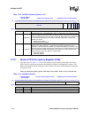
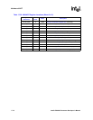
17.6 Hardware UART Register Summary
Table 17-20 contains the register addresses for the HWUART.
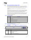
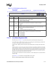
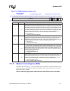
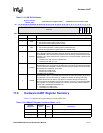
Table 17-19. ISR
Bit Definitions
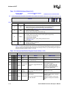
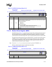
Physical Address
0x4160_0020
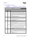
Infrared Selection Register (ISR) PXA255 Processor Hardware UART
Bit
31 30 29 28 27 26 25 24 23 22 21 20 19 18 17 16 15 14 13 12 11 10 9 8 7 6 5 4 3 2 1 0
reserved
RXPL
TXPL
XMODE
RCVEIR
XMITIR
Reset ? ? ? ? ? ? ? ? ? ? ? ? ? ? ? ? ? ? ? ? ? ? ? ? ? ? ? 0 0 0 0 0
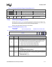
Bits Name Description
31:5 — reserved
4 RXPL
RECEIVE DATA POLARITY
0 = SIR decoder takes positive pulses as zeros
1 = SIR decoder takes negative pulses as zeros
3TXPL
TRANSMIT DATA POLARITY
0 = SIR encoder generates a positive pulse for a data bit of zero
1 = SIR encoder generates a negative pulse for a data bit of zero
2XMODE
TRANSMIT PULSE WIDTH SELECT
When XMODE is cleared, the UART 16X clock clocks the IrDA transmit and receive logic.
When XMODE is set, receive decoder operation does not change and the transmit encoder
generates 1.6
µs pulses (that are 3/16 of a bit time at 115.2 Kbps) instead of pulses 3/16 of
a bit time wide.
0 = Transmit pulse width is 3/16 of a bit time wide
1 = Transmit pulse width is 1.6
µs
1RCVEIR
RECEIVER SIR ENABLE
When RCVEIR is set, the signal from the RXD pin is processed by the IrDA decoder before
it is fed to the UART. If RCVEIR is cleared, then all clocking to the IrDA decoder is blocked
and the RXD pin is fed directly to the UART.
0 = Receiver is in UART mode
1 = Receiver is in infrared mode
0XMITIR
TRANSMITTER SIR ENABLE
When XMITIR is set to 1, the normal TXD output from the UART is processed by the IrDA
encoder before it is fed to the device pin. If XMITIR is cleared, all clocking to the IrDA
encoder is blocked and the UART’s TXD signal is connected directly to the device pin.
When Transmitter SIR Enable is set, the TXD output pin, which is in a normally high default
state, switches to a normally low default state. This can cause a false start bit unless the
infrared LED is disabled before XMITIR is set.
0 = Transmitter is in UART mode
1 = Transmitter is in infrared mode
Table 17-20. HWUART Register Locations (Sheet 1 of 2)
Register
Addresses
DLAB Bit
Value
Name Description
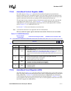
0x4160_0000 0 HWRBR “Receive Buffer Register (RBR)” (read only)
0x4160_0000 0 HWTHR “Transmit Holding Register (THR)” (write only)
0x4160_0004 0 HWIER “Interrupt Enable Register (IER)” (read/write)