


9-26 Intel® PXA255 Processor Developer’s Manual
I
2
C Bus Interface Unit
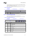
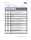
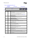
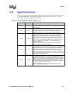
Table 9-11. ISR Bit Definitions (Sheet 1 of 2)
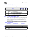
Physical Address
4030_1698
I
2
C Status Register I
2
C Bus Interface Unit
Bit
31 30 29 28 27 26 25 24 23 22 21 20 19 18 17 16 15 14 13 12 11 10 9 8 7 6 5 4 3 2 1 0
reserved
BED
SAD
GCAD
IRF
ITE
ALD
SSD
IBB
UB
ACKNAK
RWM
Reset 0 0 0 0 0 0 0 0 0 0 0 0 0 0 0 0 0 0 0 0 0 0 0 0 0 0 0 0 0 0 0 0
31:11 — reserved
10 BED
Bus Error Detected:
0 = No error detected.
1 = The I
2
C unit sets this bit when it detects one of the following error conditions:
• As a master transmitter, no ACK is detected on the interface after a byte is sent.
• As a slave receiver, the I
2
C unit generates a NAK pulse.
NOTE:When an error occurs, I
2
C bus transactions continue. Software must ensure that
misplaced START and STOP conditions do not occur. See Section 9.4.5.
To clear this bit, write a 1 to it.
9 SAD
Slave Address Detected:
0 = No slave address detected.
1 = I
2
C unit detected a 7-bit address that matches the general call address or ISAR. An
interrupt is signalled when the SADIE interrupt is set to a 1.
To clear this bit, write a 1 to it.
8GCAD
General Call Address Detected:
0 = No general call address received.
1 = I
2
C unit received a general call address.
7IRF
IDBR Receive Full:
0 = The IDBR has not received a new data byte or the I
2
C unit is idle.
1 = The IDBR register received a new data byte from the I
2
C bus. An interrupt is signalled
when the IRFIE is set to a 1.
To clear this bit, write a 1 to it.
6ITE
IDBR Transmit Empty:
0 = The data byte is still being transmitted.
1 = The I
2
C unit has finished transmitting a data byte on the I
2
C bus. An interrupt is
signalled when the ITEIE interrupt is set to 1.
To clear this bit, write a 1 to it.
5ALD
Arbitration Loss Detected: used during multi-master operation.
0 = Cleared when arbitration is won or never took place.
1 = Set when the I
2
C unit loses arbitration.
To clear this bit, write a 1 to it.
4 SSD
Slave STOP Detected:
0 = No STOP detected.
1 = Set when the I
2
C unit detects a STOP while in slave-receive or slave-transmit mode.
To clear this bit, write a 1 to it.
3IBB
I
2
C Bus Busy:
0 = I
2
C bus is idle or the I
2
C unit is using the bus (i.e., unit busy).
1 = Set when the I
2
C bus is busy but the I
2
C unit is not involved in the transaction.
2UB
Unit Busy:
0 = I
2
C unit not busy.
1 = Set when the I
2
C unit is busy. Defined as the time between the first START and STOP.