


17-14 Intel® PXA255 Processor Developer’s Manual
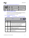
Hardware UART
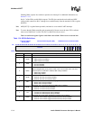
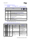
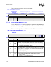
Table 17-9 shows the priority, type, and source of the Interrupt Identification register interrupts. It
also gives the reset condition used to deassert the interrupts. Bits (0-3) of the IIR register represent
priority encoded interrupts. Bits (4-7) do not.
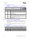
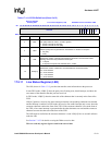
4ABL
Autobaud Lock (Section 17.4.4
):
0 = Autobaud circuitry has not programmed Divisor Latch registers (DLR).
1 = Divisor Latch registers (DLR) programmed by auto-baud circuitry.
3TOD
Time Out Detected (See Section 17.4.2.1.2, “Character Timeout Interrupt”
):
0 = No time out interrupt is pending
1 = Time out Interrupt is pending. (FIFO mode only)
2:1 IID[1:0]
Interrupt Source Encoded:
00 – Modem status (CTS, DSR, RI, DCD modem signals changed state)
01 – Transmit FIFO requests data
10 – Received data available
11 – Receive error (overrun, parity, framing, break, FIFO error.
See Table 17-17)
0nIP
Interrupt Pending:
0 = Interrupt is pending. (Active low)
1 = No interrupt is pending
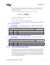
Table 17-8. IIR Bit Definitions (Sheet 2 of 2)
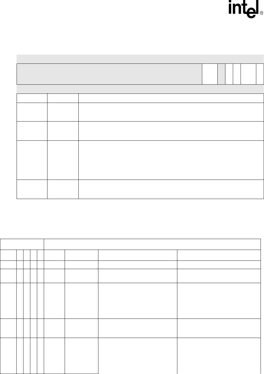
Physical Address
0x4160_0008
Interrupt Identification Register
(IIR)
PXA255 Processor Hardware UART
Bit
31 30 29 28 27 26 25 24 23 22 21 20 19 18 17 16 15 14 13 12 11 10 9 8 7 6 5 4 3 2 1 0
reserved
FIFOES
reserved
ABL
TOD
IID
nIP
Reset ? ? ? ? ? ? ? ? ? ? ? ? ? ? ? ? ? ? ? ? ? ? ? ? 0 0 ? 0 0 0 0 1
Bits Name Description
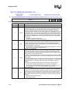
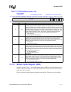
Table 17-9. Interrupt Identification Register Decode (Sheet 1 of 2)
Interrupt ID bits Interrupt SET/RESET Function
3 2 1 0 Priority Type Source RESET Control
nIP 0 0 0 1 - None No interrupt is pending. —
IID[11] 0 1 1 0 Highest
Receiver Line
Status
Overrun error, parity error, framing
error, break interrupt.
Reading the Line Status register.
IID[10] 0 1 0 0
Second
Highest
Received Data
Available.
Non-FIFO mode – Receive buffer is
full.
FIFO mode – Trigger threshold was
reached.
Non-FIFO mode – Reading the
Receiver Buffer register.
FIFO mode – Reading bytes until
receiver FIFO drops below trigger
threshold or setting RESETRF bit in
FIFO Control register (FCR).
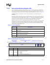
TOD 1 1 0 0
Second
Highest
Character
Timeout
indication.
FIFO mode only: At least 1 character
is left in the receive buffer indicating
trailing bytes.
Reading the receiver FIFO or setting
RESETRF bit in FCR.
IID[01] 0 0 1 0
Third
Highest
Transmit FIFO
Data Request
Non-FIFO mode: Transmit Holding
register empty
FIFO mode: transmit FIFO has half or
less than half data.
Reading the IIR (if the source of the
interrupt) or writing into the Transmit
Holding register.
Reading the IIR (if the source of the
interrupt) or writing to the transmitter
FIFO.