


16-14 Intel® PXA255 Processor Developer’s Manual
Network SSP Serial Port
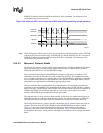
Note: If SSPSCLK is an input, the device driving SSPSCLK must provide another clock edge to cause
the TXD line to go to Hi-Z.
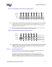
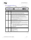
16.4.4.2 Motorola SPI
When SSCR1[TTE] is 0, the SSP behaves as described in Section 16.4.3.2.
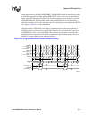
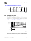
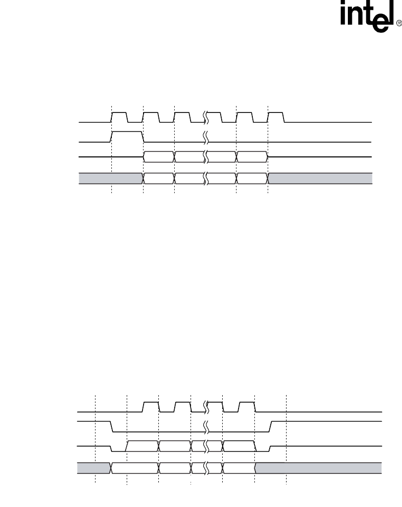
If SSCR1[TTE] is 1, SSPTXD is driven only when SSPSFRM is 0. When SSPSFRM is 1, SSPTXD
is Hi-Z. During the time between the last falling edge and SSPSFRM rising, SSPSP[EDTS]
controls the value driven on SSPTXD. Figure 16-13 shows the pin timing for this mode.
Note: SSCR1[TTELP] must be 0 for Motorola SPI.
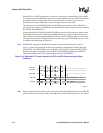
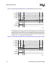
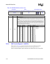
16.4.4.3 National Semiconductor Microwire
When SSCR1[TTE] is 0, the SSP behaves as described in Section 16.4.3.3.
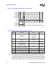
If SSCR1[TTE] is 1, SSPTXD is driven at the same clock edge that the MSB is driven. SSPTXD is
Hi-Z after the next rising edge of SSPSCLK for the LSB (1 clock edge after the clock edge that
starts the LSB). Figure 16-14 shows the pin timing for this mode.
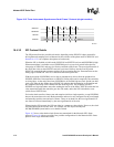
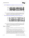
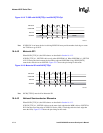
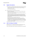
Figure 16-12. TI SSP with SSCR[TTE]=1 and SSCR[TTELP]=1
A9975-01
SSPRXD
SSPSFRM
SSPSCLK
SSPTXD
MSB 4 to 32 Bits LSB
Bit[N] Bit[N-1] Bit[1] Bit[0]
Bit[N] Bit[N-1] Bit[1] Bit[0]
Undefined Undefined
Figure 16-13. Motorola SPI with SSCR[TTE]=1
A9976-01
SSPRXD
SSPSFRM
SSPSCLK
SSPTXD
MSB LSB
Bit[N]Undefined UndefinedBit[N-1] Bit[1] Bit[0]
Bit[N] Bit[N-1] Bit[1] Bit[0]
4 to 32 Bits