


5-6 Intel® PXA255 Processor Developer’s Manual
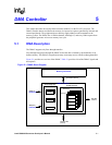
DMA Controller
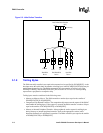
7. The channel waits for the next request or continues with the data transfer until the
DCMD[LENGTH] reaches zero.
8. The DDADR[STOP] is set to a 1 and the channel stops.
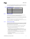
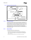
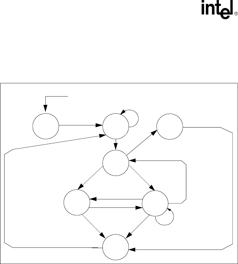
Figure 5-3 summarizes typical No-Descriptor Fetch Mode operation.
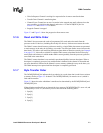
5.1.4.2 Descriptor Fetch Mode
In Descriptor Fetch Mode, the DMAC registers are loaded from DMA descriptors in main memory.
Multiple DMA descriptors can be chained together in a list. This allows a DMA channel to transfer
data to and from a number of locations that are not contiguous. The descriptor’s protocol design
allows descriptors to be added efficiently to the descriptor list of a running DMA stream.
A typical Descriptor Fetch Mode (DCSR[NODESCFETCH] = 0) operation follows:
1. The channel is in an uninitialized state after reset.
2. The software writes a descriptor address (aligned to a 16-byte boundary) to the DDADR
register.
3. The software writes a 1 to the DCSR[RUN] bit.
4. The DMAC fetches the four-word descriptor (assuming that the memory is already set up with
the descriptor chain) from the memory indicated by DDADR.
5. The four-word DMA descriptor, aligned on a 16-byte boundary in main memory, loads the
following registers:
Figure 5-3. No-Descriptor Fetch Mode Channel State
DCSR[RUN]=0,
DCSR[NODESCFETCH]=1,
DSADR,DTADR,
DCMD programmed
Uninitialized
Valid
RESET
(Hardware or Sleep)
not running
(running)
Wa i t
for
request
Transferring
Data
Stopped
descriptor
Error
Channel
RUN=1
DCMD[LENGTH] 0
& DCMD[FLOWSRC] = 0
& DCMD[FLOWTRG] = 0
DDADR[STOP] = 1
DDADR[STOP] = 1
DCMD[FLOWSRC] xor
DCMD[FLOWTRG] = 1
DCMD[FLOWSRC] &
DCMD[FLOWTRG] = 0
Request Asserted
DDADR[STOP] = 0
DCMD[FLOWSRC] xor
DCMD[FLOWTRG] = 1
No
descriptor
fetch
RUN=0
RUN=0
≠