


15-6 Intel® PXA255 Processor Developer’s Manual
MultiMediaCard Controller
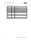
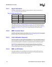
15.2.1 Signal Description
The MMC controller signals are MMCLK, MMCMD, MMDAT, MMCCS0, and MMCCS1.
Table 15-4 describes each signal’s function.
The MMCLK, MMCCS0, and MMCCS1 signals are routed through alternate functions within the
GPIO. Refer to Section 4.1, “General-Purpose I/O” on page 4-1 for a description of the process
used to assign these signals to a specific GPIO. Even though there are several GPIO assigned to
each signal, each signal must be programmed to one of the possible GPIOs. Refer to Section 4.1.2,
“GPIO Alternate Functions” on page 4-2 for a complete description of the GPIO alternate
functions.
15.2.2 MMC Controller Reset
The MMC controller can only be reset by a hard or soft reset of the processor. The ways to reset the
processor and the MMC controller can be found in Section 2.6, “Reset” on page 2-6. All registers
and FIFO controls are set to their default values after any reset.
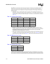
15.2.3 Card Initialization Sequence
After reset, the MMC card must be initialized by sending 80 clocks to it on the MMCLK signal. To
initialize the MMC card, set the MMC_CMDAT[INIT] bit to a 1. This sends 80 clocks before the
current command in the MMC_CMD register. This function is useful for acquiring new cards that
have been inserted on the bus. Chip selects are not asserted during the initialization sequence.
After the 80-clock initialization sequence, the software must continuously send CMD1 (see
Table 15-18 for command definitions) by loading the appropriate command index into the
MMC_CMD register until the card indicates that the power-up sequence is complete. The software
can then assign an address to the card or put it into SPI mode.
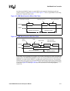
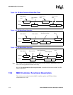
15.2.4 MMC and SPI Modes
After reset, the MMC card is in the MMC mode. The card may remain in MMC mode or be
configured to SPI mode by setting the MMC_SPI register bits. The following sections briefly
describe each mode as it pertains to the MMC controller.
Table 15-4. MMC Signal Description
Signal Name Input/Output Description
MMCLK Output Clock signal to MMC
MMCMD BiDirectional Command line
MMDAT BiDirectional Data line
MMCCS0 Output Chip Select 0 (used only in SPI mode)
MMCCS1 Output Chip Select 1 (used only in SPI mode)