


Intel® PXA255 Processor Developer’s Manual 15-3
MultiMediaCard Controller
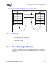
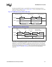
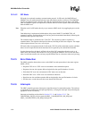
the bidirectional MMDAT signal. A typical MMC mode command timing diagram with and
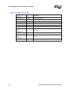
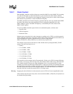
without a response is shown in Figure 15-2 while Figure 15-3 shows a typical MMC mode timing
diagram for a sequential read or write
.
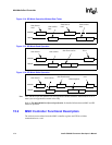
In SPI mode, not all commands are available. The available commands have both a command and
response token. The MMCMD and MMDAT signals are no longer bidirectional in SPI mode. The
MMCMD is an output and the MMDAT is an input with respect to the processor. The command
and data tokens to be written are sent on the MMCMD signal and the response and read data tokens
are received on the MMDAT signal. Figure 15-4 shows a typical SPI mode timing diagram without
a data token. Figure 15-5 and Figure 15-6 show SPI mode read and write timing diagrams,
respectively.
Figure 15-2. MMC Mode Operation Without Data Token
Figure 15-3. MMC Mode Operation With Data Token
Command
MMCMD
MMDAT
Operation (No Response) Operation (No Data)
Command Response
from host to card(s) from card to hostfrom host to card
Command
MMCMD
MMDAT
Data Transfer Operation
Data Stop Operation
Response
Data Stream
from
host to
from
stop command
stops data transfer
Command Response
data to/from