


Intel® PXA255 Processor Developer’s Manual 10-19
UARTs
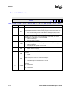
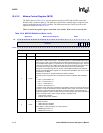
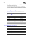
10.4.2.10 Modem Status Register (MSR)
The MSR, shown in Table 10-15, provides the current state of the control lines from the modem or
data set (or a peripheral device emulating a modem) to the processor. In addition to this current
state information, four bits of the MSR provide change information. MSR[3:0] are set when a
control input from the Modem changes state. They are cleared when the processor reads the MSR.
Differences between UARTs specific to this register are described in Section 10.5.1.
The status of the modem control lines do not affect the FIFOs. To use these lines for flow control,
IER[MIE] must be set. When an interrupt on one of the flow control pins occurs, the interrupt
service routine must disable the UART. The UART will continue transmission/reception of the
current character and then stop. The contents of the FIFOs will be preserved. If the UART is re-
enabled, transmission will continue where it stopped. Interrupts from the flow control pins will not
come through the UART unit if the unit is disabled. When disabling the unit because of flow
control, interrupts must be enabled in the processor Interrupt Controller for the flow control pins.
The Interrupt Controller will still trigger interrupts if the pins are in Alternate Function Mode.
Note: When bit 0, 1, 2, or 3 is set, a Modem Status interrupt is generated if IER[MIE] is set.
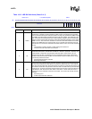
This is a read-only. Ignore reads from reserved bits.
2OUT1
Test bit. This bit is used only in Loopback mode. It is ignored otherwise.
0 – Force MSR[RI] to 0
1 – Force MSR[RI] to 1
1RTS
Request to Send.
0 – nRTS pin is 1
1 – nRTS pin is 0
0DTR
Data Terminal Ready.
0 – nDTR pin is 1
1 – nDTR pin is 0
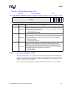
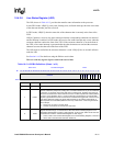
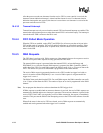
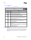
Table 10-14. MCR Bit Definitions (Sheet 2 of 2)
Base+0x10 Modem Control Register UART
Bit
31 30 29 28 27 26 25 24 23 22 21 20 19 18 17 16 15 14 13 12 11 10 9 8 7 6 5 4 3 2 1 0
reserved
LOOP
OUT2
OUT1
RTS
DTR
Reset 0 0 0 0 0 0 0 0 0 0 0 0 0 0 0 0 0 0 0 0 0 0 0 0 0 0 0 0 0 0 0 0
Read/Write
Bits Name Description