


14-14 Intel® PXA255 Processor Developer’s Manual
Inter-Integrated-Circuit Sound (I2S) Controller
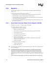
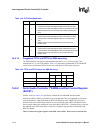
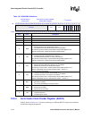
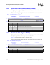
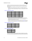
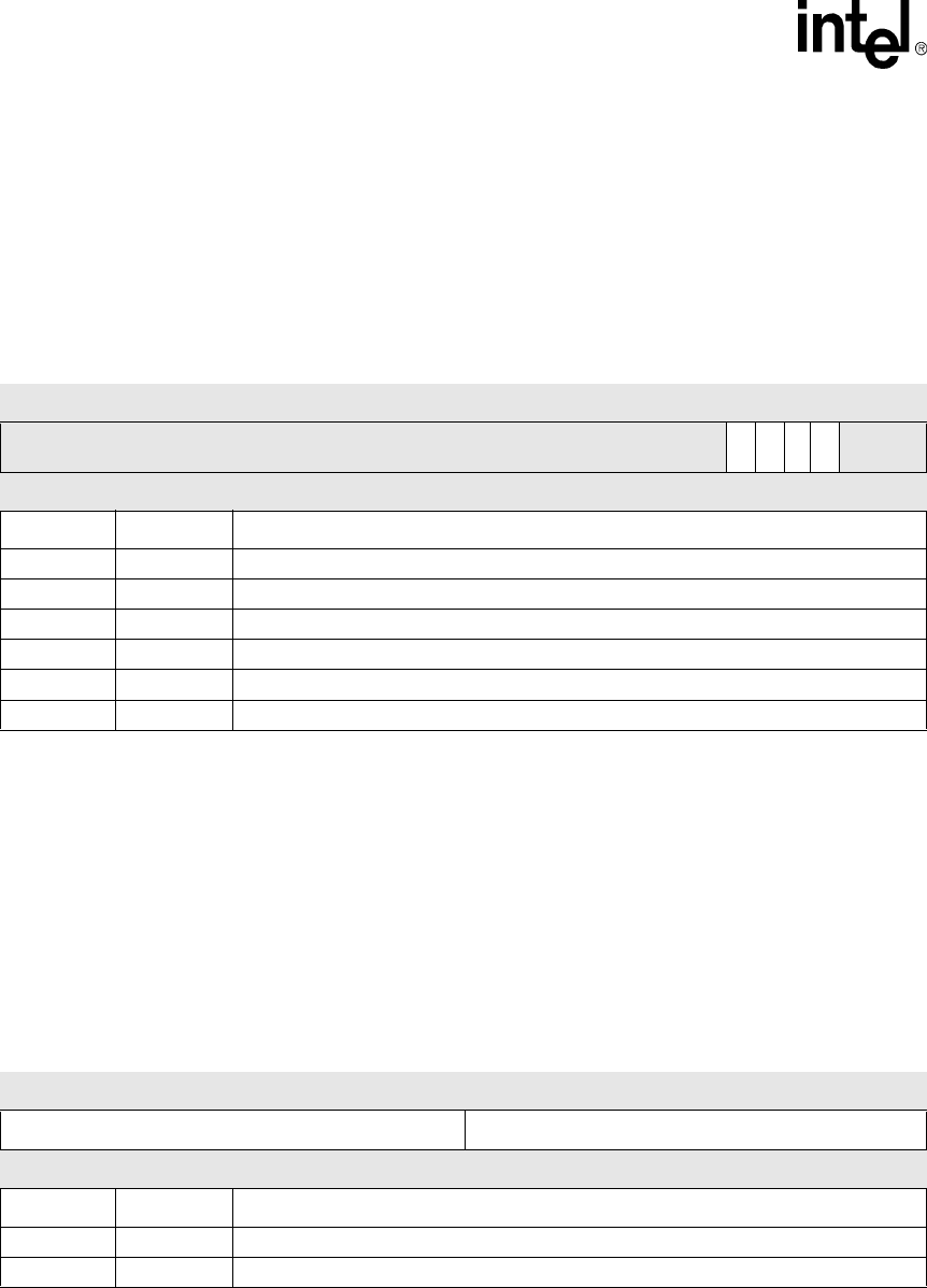
14.6.6 Serial Audio Interrupt Mask Register (SAIMR)
Writing a one to the corresponding bit position in the SAIMR, shown in Table 14-10, enables the
corresponding interrupt signal.
This is a read/write register. Ignore reads from reserved bits. Write zeros to reserved bits.
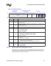
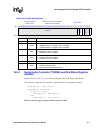
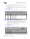
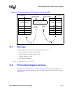
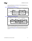
14.6.7 Serial Audio Data Register (SADR)
Writing a 32-bit sample to SADR, shown in Table 14-11, updates the data into the Transmit FIFO.
Reading this register flushes a 32-bit sample from the Receive FIFO.
Figure 14-3 illustrates data flow through the FIFOs and SADR.
This is a read/write register. Ignore reads from reserved bits. Write zeros to reserved bits.
Table 14-10. SAIMR Bit Descriptions
Physical Address
0x4040_0014
Serial Audio Interrupt Mask Register I
2
S Controller
Bit
31 30 29 28 27 26 25 24 23 22 21 20 19 18 17 16 15 14 13 12 11 10 9 8 7 6 5 4 3 2 1 0
reserved
ROR
TUR
RFS
TFS
reserved
Reset
0 0 0 0 0 0 0 0 0 0 0 0 0 0 0 0 0 0 0 0 0 0 0 0 0 0 0 0 0 0 0 0
Bits Name Description
31:7 — reserved
6 ROR Enable Receive FIFO Overrun condition based interrupt.
5 TUR Enable FIFO Under-run condition based interrupt.
4 RFS Enable Receive FIFO Service Request based interrupt.
3 TFS Enable Transmit FIFO Service Request based interrupt.
2:0 — reserved
Table 14-11. SADR Bit Descriptions
Physical Address
0x4040_0080
Serial Audio Data Register I
2
S Controller
Bit
31 30 29 28 27 26 25 24 23 22 21 20 19 18 17 16 15 14 13 12 11 10 9 8 7 6 5 4 3 2 1 0
DTH DTL
Reset
0 0 0 0 0 0 0 0 0 0 0 0 0 0 0 0 0 0 0 0 0 0 0 0 0 0 0 0 0 0 0 0
Bits Name Description
31:16 DTH Right data sample
15:0 DTL Left data sample