


Intel® PXA255 Processor Developer’s Manual 17-3
Hardware UART
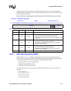
17.3 Signal Descriptions
Table 17-1 lists and describes each external signal that is connected to the UART module. The pins
are connected to the PXA255 processor through GPIOs.
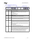
17.4 Operation
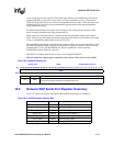
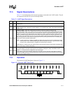
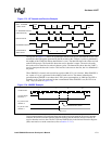
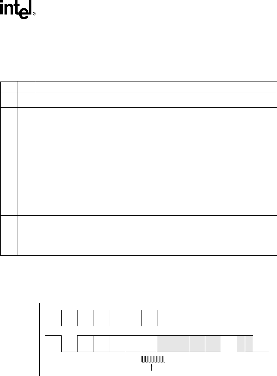
The format of a UART data frame is shown in Figure 17-1.
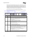
Table 17-1. UART Signal Descriptions
Name Type Description
RXD Input
SERIAL INPUT – Serial data input to the receive shift register. In infrared mode, it is connected to the infrared
receiver input.
TXD Output
SERIAL OUTPUT – Serial data output to the communications link-peripheral, modem, or data set. The TXD
signal is set to the logic 1 state upon a Reset operation. It is connected to the output of the infrared transmitter in
infrared mode.
nCTS Input
CLEAR TO SEND – When low, indicates that the modem or data set is ready to exchange data.
Non-Autoflow Mode: When not in autoflow mode, bit 4 (CTS) of the Modem Status register (MSR) indicates the
state of nCTS. Bit 4 is the complement of the nCTS signal. Bit 0 (DCTS) of the Modem Status register indicates
whether the nCTS input has changed state since the previous reading of the Modem Status register. When the
CTS bit of the MSR changes state and the modem status interrupt is enabled, an interrupt is generated. nCTS
has no effect on the transmitter. The user can program the UART to interrupt the processor when DCTS changes
state. The programmer can then stall the outgoing data stream by starving the transmit FIFO or disabling the
UART with the Interrupt Enable register (IER).
NOTE:
If UART transmission is stalled by disabling the UART, the user will not receive an MSR interrupt when
nCTS reasserts. This is because disabling the UART also disables interrupts. To get around this, either
use Auto CTS in Autoflow Mode, or program the nCTS GPIO pin to interrupt.
Autoflow Mode: In autoflow mode, the UART transmit circuity checks the state of nCTS before transmitting each
byte. If nCTS is high, no data is transmitted.
nRTS Output
REQUEST TO SEND – When low, signals the modem or the data set that the UART is ready to exchange data.
Non-Autoflow Mode: The nRTS output signal can be asserted by setting bit 1 (RTS) of the Modem Control
register to 1. The RTS bit is the complement of the nRTS signal.
Autoflow Mode: nRTS is automatically asserted by the autoflow circuitry when the receive buffer exceeds its
programmed trigger threshold. It is deasserted when enough bytes are removed from the buffer to lower the data
level back to the trigger threshold.
Figure 17-1. Example UART Data Frame
Start
Bit
Data
<0>
Data
<1>
Data
<2>
Data
<3>
Data
<4>
Data
<5>
Data
<6>
Data
<7>
Parity
Bit
Stop
Bit 1
Stop
Bit 2
TXD or RXD pin
LSB MSB