Intel® PXA255 Processor Developer’s Manual 4-35
System Integration Unit
also routed to the interrupt controller where they can be programmed to cause an interrupt. OSMR3
also serves as a watchdog match register that resets the processor when a match occurs provided
the OS Timer Watchdog Match Enable Register (OWER) is set. You must initialize the OSCR and
OSMR registers and clear any set status bits before the FIQ and IRQ interrupts are enabled within
the CPU.
4.4.1 Watchdog Timer Operation
The OSMR3 can also be used as a watchdog compare register. This function is enabled by setting
OWER[0]. When a compare against this register occurs and the watchdog is enabled, reset is
applied to the processor and most internal states are cleared. Internal reset is asserted for 256
processor clocks and then removed, allowing the processor to boot. See Section 3.4.2, “Watchdog
Reset” on page 3-7 for details on reset functionality.
The following procedure is suggested when using OSMR3 as a watchdog
– each time the operating
system services the register:
1. The current value of the counter is read.
2. An offset is then added to the read value. This offset corresponds to the amount of time before
the next time-out (care must be taken to account for counter wraparound).
3. The updated value is written back to OSMR3.
The OS code must repeat this procedure periodically before each match occurs. If a match occurs,
the OS timer asserts a reset to the processor.
4.4.2 OS Timer Register Definitions
4.4.2.1 OS Timer Match Register 0-3 (OSMRx)
These registers are 32-bits wide and are readable and writable by the processor. They are compared
against the OSCR after every rising edge of the 3.6864 MHz clock. If any of these registers match
the counter register, and the appropriate interrupt enable bit is set, then the corresponding status bit
in the OSSR is set. The status bits are routed to the interrupt controller where they can be unmasked
to cause a CPU interrupt. The OSMR3 can also be used as a watchdog timer.
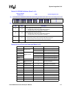
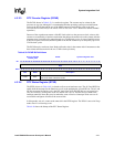
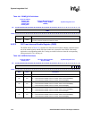
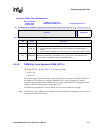
Table 4-41 shows the bitmap of the OS Timer Match register. All four registers are identical, except
for location. A single, generic OS Timer match register is described, but all information is common
to all four OS Timer Match Registers.


