


Intel® PXA255 Processor Developer’s Manual 12-45
USB Device Controller
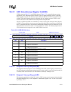
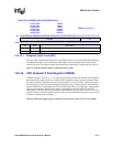
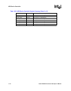
12.6.15.1 Endpoint x Byte Count (BC)
The byte count is updated after each byte is read. When software receives an interrupt that indicates
the endpoint has data, it can read the byte count register to determine the number of bytes that
remain to be read. The number of bytes that remain in the input buffer is equal to the byte count +1.
This is a read-only register. Ignore reads from reserved bits.
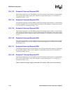
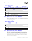
12.6.16 UDC Endpoint 0 Data Register (UDDR0)
UDDR0, shown in, Table 12-27, is a 16-entry by 8-bit bidirectional FIFO. When the host transmits
data to the UDC Endpoint 0, the core reads the UDC endpoint 0 register to access the data. When
the UDC sends data to the host, the core writes the data to be sent in the UDC endpoint 0 register.
The core can only read and write the FIFO at specific points in a control sequence. The direction
that the FIFO flows is controlled by the UDC. Normally, the UDC is in an idle state, waiting for the
host to send commands. When the host sends a command, the UDC fills the FIFO with the
command from the host and the core reads the command from the FIFO when it arrives. The only
time the core may write the endpoint 0 FIFO is after a valid command from the host is received and
it requires a transmission in response.
This is a read/write register. Ignore reads from reserved bits. Write zeros to reserved bits.
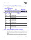
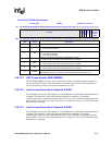
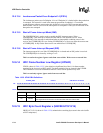
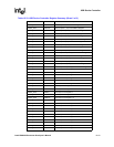
Table 12-26. UBCR2/4/7/9/12/14 Bit Definitions
0x 4060_0068
0x 4060_006C
0x 4060_0070
0x 4060_0074
0x 4060_0078
0x 4060_007C
UBCR2
UBCR4
UBCR7
UBCR9
UBCR12
UBCR14
USB Device Controller
Bit
31 30 29 28 27 26 25 24 23 22 21 20 19 18 17 16 15 14 13 12 11 10 9 8 7 6 5 4 3 2 1 0
reserved BC
Reset x x x x x x x x x x x x x x x x x x x x x x x x 0 0 0 0 0 0 0 0
Bits Name Description
31:8 — reserved
7:0 BC Byte Count (read-only). Number of bytes in the FIFO is Byte Count plus 1 (BC+1).