


Intel® PXA255 Processor Developer’s Manual 12-3
USB Device Controller
12.3.1 Signalling Levels
USB uses differential signalling to encode data and to indicate various bus conditions. The USB
specification refers to the J and K data states to differentiate between high- and low-speed
transmissions. Because the UDC supports only 12 Mbps transmissions, references are only made to
actual data state 0 and actual data state 1.
By decoding the polarity of the UDC+ and UDC- pins and using differential data, four distinct
states are represented. Two of the four states are used to represent data. A 1 indicates that UDC+ is
high and UDC- is low. A 0 indicates that UDC+ is low and UDC- is high. The two remaining states
and pairings of the four encodings are further decoded to represent the current state of the USB.
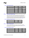
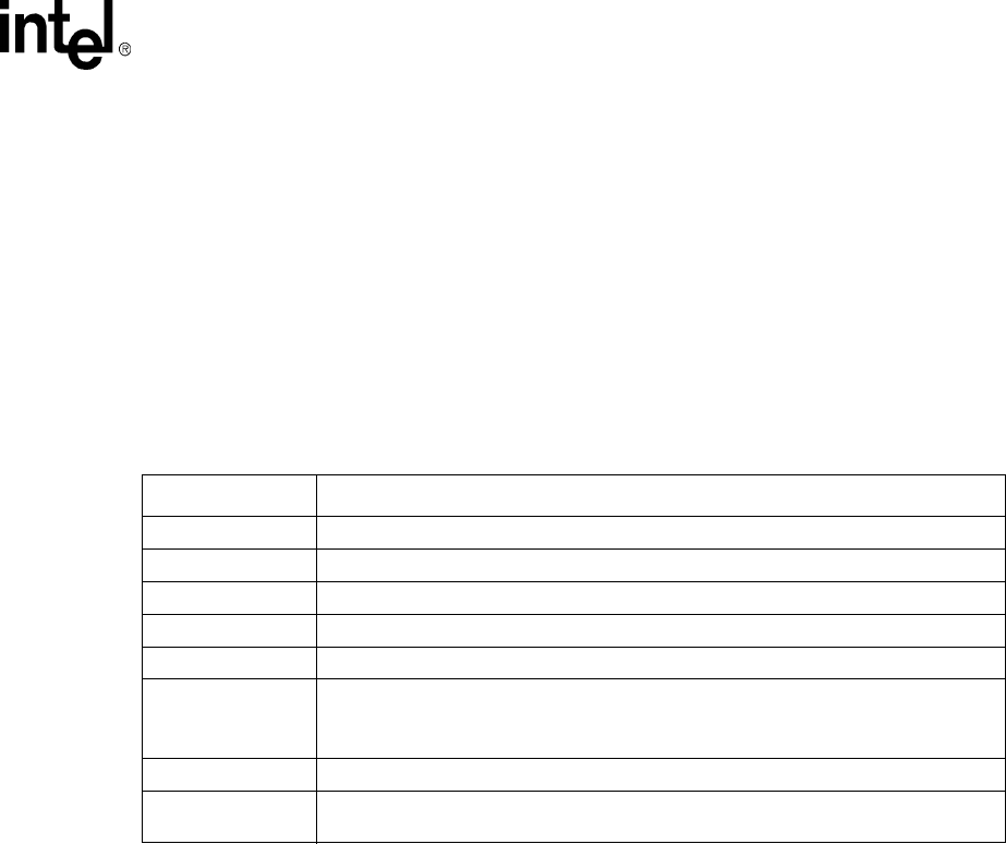
Table 12-2 shows how differential signalling represents eight different bus states.
Hosts and hubs have pull-down resistors on both the D+ and D- lines. When a device is not
attached to the cable, the pull-down resistors cause D+ and D- to be pulled down below the single-
ended low threshold of the host or hub. This creates a state called single-ended zero (SE0). The
host detects a disconnect when an SE0 persists for more than 2.5 µs (30 bit times). When the UDC
is connected to the USB cable, the pull-up resistor on the UDC+ pin causes D+ to be pulled above
the single-ended high threshold level. After 2.5 µs, the host detects a connect.
After the host detects a Connect, the bus is in the Idle state because UDC+ is high and UDC- is low.
The bus transitions from the Idle state to the Resume state (a 1 to 0 transition) to signal the Start of
Packet (SOP). Each USB packet begins with a Sync field that starts with the 1-to-0 transition (see
Section 12.3.1). After the packet data is transferred, the bus signals the End of Packet (EOP) state
by pulling both UDC+ and UDC- low for 2 bit times followed by an Idle state for 1 bit time. If the
idle persists for more than 3 ms, the UDC enters Suspend state and is placed in low-power mode.
The host can awaken the UDC from the Suspend state by signalling a reset or by switching the bus
to the resume state via normal bus activity. Under normal operating conditions, the host
periodically signals an Start of Frame (SOF) to ensure that devices do not enter the suspend state.
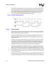
12.3.2 Bit Encoding
USB uses nonreturn to zero inverted (NRZI) to encode individual bits. Both the clock and the data
are encoded and transmitted in the same signal. Data is represented by transitions rather than by the
signal’s state. A zero is represented by a transition, and a one is represented by no transition, which
produces the data. Each time a zero occurs, the receiver logic synchronizes the baud clock to the
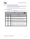
Table 12-2. USB States
Bus State UDC+/UDC- Pin Levels
Idle
UDC+ high, UDC- low (same as a 1).
Suspend
Idle state for more than 3 ms.
Resume
UDC+ low, UDC- high (same as a 0).
Start of Packet
Transition from idle to resume.
End of Packet
UDC+ AND UDC- low for 2 bit times followed by an idle for 1 bit time.
Disconnect
UDC+ AND UDC- below single-ended low threshold for more than 2.5 µs.
(Disconnect is the static bus condition that results when no device is plugged into a hub
port.)
Connect
UDC+ OR UDC- high for more than 2.5 µs.
Reset
UDC+ AND UDC- low for more than 2.5 µs. (Reset is driven by the host controller and
sensed by a device controller.)