


12-2 Intel® PXA255 Processor Developer’s Manual
USB Device Controller
12-Mbps device and provides the correct polarity for data transmission. The serial bus uses
differential signalling to transmit multiple states simultaneously. These states are combined to
produce transmit data and various bus conditions, including: Idle, Resume, Start of Packet, End of
Packet, Disconnect, Connect, and Reset.
12.2 Device Configuration
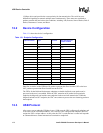
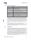
Table 12-1 shows the device’s configuration.
Data flow is relative to the USB host. IN packets represent data flow from the UDC to the host.
OUT packets represent data flow from the host to the UDC.
The FIFOs for the Bulk and Isochronous endpoints are double-buffered so one packet can be
processed as the next is assembled. While the UDC transmits an IN packet from a particular
endpoint, the Megacell can load the same endpoint for the next frame transmission. While the
Megacell unloads an OUT endpoint, the UDC can continue to process the next incoming packet to
that endpoint.
12.3 USB Protocol
After a core reset or when the USB host issues a USB reset, the UDC configures all endpoints and
is forced to use the USB default address, zero. After the UDC configures the endpoints, the host
assigns the UDC a unique address. At this point, the UDC is under the host’s control and responds
to commands that use control transactions to transmit to endpoint 0.
Table 12-1. Endpoint Configuration
Endpoint Number Type Function
FIFO Size (bytes) X
number of FIFOs
0 Control IN/OUT 16
1BulkIN64x2
2 Bulk OUT 64x2
3 Isochronous IN 256x2
4 Isochronous OUT 256x2
5 Interrupt IN 8
6BulkIN64x2
7 Bulk OUT 64x2
8 Isochronous IN 256x2
9 Isochronous OUT 256x2
10 Interrupt IN 8
11 Bulk IN 64x2
12 Bulk OUT 64x2
13 Isochronous IN 256x2
14 Isochronous OUT 256x2
15 Interrupt IN 8