


Intel® PXA255 Processor Developer’s Manual 16-23
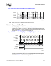
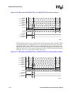
Network SSP Serial Port
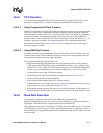
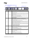
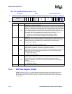
Table 16-5. SSPSP Bit Definitions (Sheet 1 of 2)
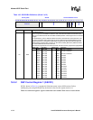
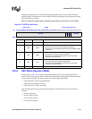
0x4140_002C SSPSP Network SSP Serial Port
Bit 31 30 29 28 27 26 25 24 23 22 21 20 19 18 17 16 15 14 13 12 11 10 9 8 7 6 5 4 3 2 1 0
reserved
DMYSTOP
reserved
SFRMWDTH SFRMDLY
DMYSTRT
STRTDLY
ETDS
SFRMP
SCMODE
Reset ? ? ? ? ? ? ? 0 0 ? 0 0 0 0 0 0 0 0 0 0 0 0 0 0 0 0 0 0 0 0 0 0
Bits Name Description
31:25 — reserved
24:23 DMYSTOP
DUMMY STOP
Determines the number of serial clock (SSPSCLK) cycles that SSPSCLK is active following the
last bit (bit 0) of transmitted (SSPTXD) or received data (SSPRXD).
22:16 SFRMWDTH
SERIAL FRAME WIDTH:
Determines the number of serial clock periods of the frame width (SSPSFRM active).
The programmed value must not be greater than:
(Start Delay)
max
+ (Dummy start)
max
+ (Data size)
max
+ (Dummy Stop)
max
.
In slave mode (SSCR1[SFRMDIR] set), this field is ignored, however the incoming frame signal
must be asserted for at least 1 SSPSCLK duration.
In PSP mode, the incoming frame signal must be deasserted for at least 1 SSPSCLK after
assertion (before the next sample is transferred).
15:9 SFRMDLY
SERIAL FRAME DELAY:
Determines the number of half serial clock periods that SSPSFRM is delayed from the start of
the transfer. The programed value sets the number of half SSPSCLK cycles from the time TXD/
RXD starts being driven to the time SSPSFRM is asserted, from 0 to 74.
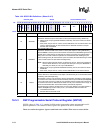
8:7 DMYSTRT
DUMMY START:
Determines the number of SSPSCLK cycles after STRTDLY that precede the transmitted
(SSPTXD) or received data (SSPRXD).
6:4 STRTDLY
THREE-BIT START DELAY FIELD:
Determines the number of SSPSCLK cycles that SSPSCLK remains in its Idle state between
data transfers. The start delay field must be programmed to 0 whenever SSPSCLK or
SSPSFRM is configured as an input (SSCR1[SCLKDIR] = 1 or SSCR1[SFRMDIR] = 1).
3ETDS
END OF TRANSFER DATA STATE:
Determines the state of SSPTXD at the end of a transfer. When cleared, the state of SSPTXD is
forced to 0 after the last bit (bit 0) of the frame is sent and remains 0 through the next idle period.
When set, the state of SSPTXD retains the value of the last bit sent (bit 0) through the next idle
period.
0 – Low
1 – Last Value <Bit 0>
2SFRMP
SERIAL FRAME POLARITY:
Determines the active state of the Serial Frame signal (SSPSFRM).
In Idle mode or when the SSP is disabled, SSPSFRM is in its inactive state. In slave mode
(SSCR1[SFRMDIR] set), this bit indicates the polarity of the incoming frame signal.
0 – SSPSFRM is active low.
1 – SSPSFRM is active high.