


Intel® PXA255 Processor Developer’s Manual 4-39
System Integration Unit
4.5.1.1 Interdependencies
The PWM unit is clocked off the 3.6864 MHz oscillator output.
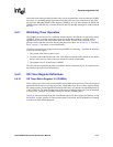
Each Pulse Width Modulator Unit (PWMn) is controlled by three registers:
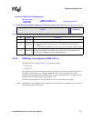
• Pulse Width Control Register (PWM_CTRL)
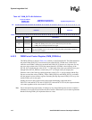
• Duty Cycle Control Register (PWM_DUTY)
• Period Control Register (PWM_PERVAL)
By setting the values in these registers the PWMn unit produces a pulse width modulated output
signal. The registers contain the values for PWMn’s counters and PWMn power management
mode.
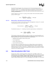
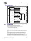
Each register contains one or more fields which determine an attribute of the PWM_OUTn
waveform. PWM_CTRLn[PRESCALE] specifies the divisor for the PWM module clock. Note
that the actual PWM module clock divisor used is 1 greater than the value programmed into
PWM_CTRLn[PRESCALE]. This divided PWM module clock drives a 10 bit up-counter. This up-
counter feeds 2 separate comparators. The first comparator contains the value of
PWM_DUTYn[DCYCLE]. When the values match, the PWM_OUT signal is set high. The other
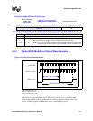
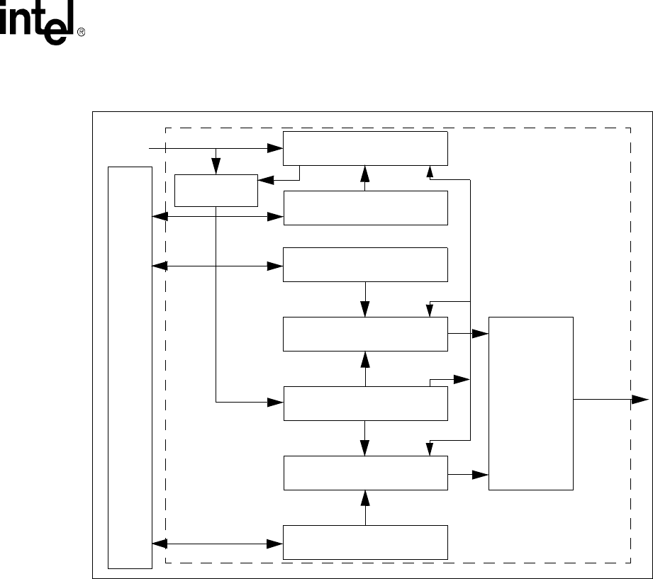
Figure 4-3. PWMn Block Diagram
Value of
PWM_DUTYn[DCYCLE]
Comparator
10-bit up counter
Comparator
Value of
PWM_PERVALn[PV]
Value of
PWM_CTRLn[PRESCALE]
6-bit down counter
Clock Gate
PSCLK_PWMn
PWM_OUTn
RESET
SET
FLIP-FLOP
3.6864 MHz
Bus
Interfac
Control Block