


3-20 Intel® PXA255 Processor Developer’s Manual
Clocks and Power Manager
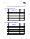
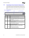
3.4.10 Power Mode Summary
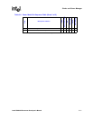
Table 3-4 shows the actions that occur when a Power Mode is entered. Table 3-5 shows the actions
that occur when a Power Mode is exited. In the tables, an empty cell means that the power mode
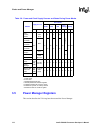
skips that step. Table 3-6 shows the expected behavior for power supplies in each power mode.
.
Table 3-4. Power Mode Entry Sequence Table
Step
Description of Action
Turbo
Run (from Turbo)
Idle
Freq Change
Sleep
Fault
1
Sleep
1 Software writes a bit in CP14 x x x x x
2 The CPU waits until all instructions to be completed x x x x x
3 Wake up sources are cleared and limited to GP[1:0] x
4 The PM places GPIOs in their sleep states x x
5 The Memory Controller finishes all outstanding transactions x x x
6 The Memory Controller places SDRAMs in self-refresh x x x
7 The PLL is disabled x x x
8 If OPDE and OOK bits are set, disable 3.6864 MHz oscillator x x
9 Internal Reset to most modules. nRESET_OUT asserted x x
10 PWR_EN is deasserted. Power is cut off x x
11 Power to most I/O pins is cut off
1: Fault Sleep Mode starts if IDAE is clear and nBATT_FAULT or nVDD_FAULT is asserted.
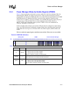
Table 3-5. Power Mode Exit Sequence Table (Sheet 1 of 2)
Step
Description of Action
Turbo
Run (from Turbo)
Idle
Freq Change
Sleep
Fault
1
Sleep
1 Wake up source or Interrupt is received x x x
2 Power to I/O pins restored
3 PWR_EN is asserted x x
4 External power ramp x x
5 Enable 3.6864 MHz oscillator if OPDE and OOK are set x x
6
Wait for 3.6864 MHz oscillator to stabilize if OPDE and OOK
are set
xx
7 Enable PLL with new frequency x x x
8 Wait for PLL stabilization x x x
9 Wait for internal stabilization x x
10 Clear CP14 bit x x