


7-28 Intel® PXA255 Processor Developer’s Manual
LCD Controller
This is a read/write register. Ignore reads from reserved bits. Write zeros to reserved bits.
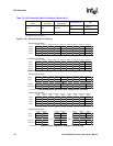
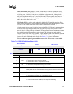
7.6.4 LCD Controller Control Register 3 (LCCR3)
LCCR3, shown in Table 7-6, contains bits and bit fields used to control various functions within
the LCD controller.
Double Pixel Clock (DPC) — doubles the rate of the pixel clock on the L_PCLK pin. This allows
direct connection to an NTSC encoder (e.g., the Analog Devices 7171). All of the LCD controller
settings are still specified in terms of the “original” pixel clock and this mode affects only the
L_PCLK output pin. If DPC is set to 1, the pixel clock divisor (PCD) must be greater than or equal
to 1.
Bits Per Pixel (BPP) — BPP specifies the size of encoded pixel values in memory. Pixel sizes of
1, 2, 4, and 8 bits require that the internal palette RAM be loaded before pixels can be displayed on
the screen. See Section 7.6.5 for details on programming the DMAC to load the palette RAM. BPP
is programmed as follows:
0b000 = 1-bit pixels
0b001 = 2-bit pixels
0b010 = 4-bit pixels
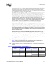
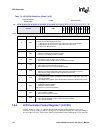
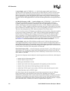
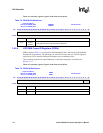
Table 7-5. LCCR2 Bit Definitions
Physical Address
0x4400_0008
LCD Controller Control Register 2 LCD Controller
Bit
31 30 29 28 27 26 25 24 23 22 21 20 19 18 17 16 15 14 13 12 11 10 9 8 7 6 5 4 3 2 1 0
BFW EFW VSW LPP
Reset
0 0 0 0 0 0 0 0 0 0 0 0 0 0 0 0 0 0 0 0 0 0 0 0 0 0 0 0 0 0 0 0
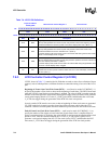
Bits Name Description
31:24 BFW
Beginning-of-frame line clock wait count:
In active mode (LCCR0[PAS]=1), value (0–255) specifies the number of line clock periods
to add to the beginning of a frame before the first set of pixels is sent to the display. The
Line clock does toggle during the insertion of the extra line clock periods.
BFW must be cleared to zero (disabled) in passive mode.
23:16 EFW
End-of-frame line clock wait count:
In active mode (LCCR0[PAS] = 1), value (0–255) specifies the number of line clock periods
to add to the end of each frame. The Line clock does toggle during the insertion of the extra
line clock periods.
EFW must be cleared to zero (disabled) in passive mode.
15:10 VSW
Vertical sync pulse width:
In active mode (LCCR0[PAS] = 1), value (0–63) specifies the number of line clock periods
to pulse the L_FCLK pin at the end of each frame after the end-of-frame wait (EFW) period
elapses. Frame clock used as VSYNC signal in active mode. The line clock does toggle
during VSYNC. VSYNC width = (VSW+1)
In passive mode (LCCR0[PAS] = 0), value (0–63) specifies the number of extra line clock
periods to insert after the end-of-frame. The time for which L_FCLK is asserted is not
affected by VSW in passive mode. The line clock does toggle during the insertion of the
extra line clock periods. VSYNC width = (VSW+1).
9:0 LPP
Lines per panel:
Specifies the number of lines per panel. For single-panel mode, this represents the total
number of lines on the LCD display. For dual-panel mode, it is half the number of lines on
the whole LCD display. Lines per panel = (LPP+1).