7-38 Intel® PXA255 Processor Developer’s Manual
LCD Controller
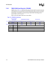
7.6.7 LCD Controller Status Register (LCSR)
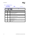
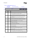
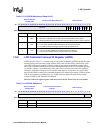
LCSR, shown in Table 7-12, contains bits that signal:
• Underrun errors for both the input and output FIFOs
• AC bias pin transition count
• LCD disable and quick disable
• DMA start/end frame and branch status
• DMA transfer bus error conditions.
Unless masked, each of these hardware-detected events signals an interrupt request to the interrupt
controller. Two bits, BER and ABC, generate nonmaskable interrupts.
Each of the LCD’s status bits continues to signal an interrupt request for as long as the bit is set.
Once the bit is cleared, the interrupt is cleared. Status bits are referred to as sticky (once set by
hardware, they must be cleared by software). Writing one to a sticky status bit clears it. Writing
zero has no effect. All LCD interrupts can be masked by programming the Interrupt Controller
Mask Register (ICMR). See Section 4.2, “Interrupt Controller” on page 4-20 for more details.
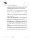
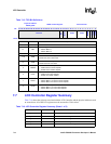
Subsequent Interrupt Status (SINT) — set when an unmasked interrupt occurs and there is
already a pending interrupt. The frame ID of the first interrupt is saved in the LCD controller
interrupt ID register (LIIDR). SINT is set only for bus error, start of frame, end of frame, and
branch status interrupts.
Note: If a branched-to descriptor has SOF set, both the SOF and branch interrupts are signalled at the
same time, and SINT is not set.
Branch Status (BS) — set after the DMA controller has branched and loaded the descriptor from
the frame branch address in the frame branch register, and the branch interrupt (BINT) bit in the
frame branch register is set. When BS is set, an interrupt request is made to the interrupt controller
if it is unmasked (LCCR0[BM] = 0).
In dual-panel mode (LCCR0[SDS = 1]), both DMA channels are enabled, and BS is set only after
both channels’ frames have been fetched. BS remains set until cleared by software.
End Of Frame Status (EOF) — set after the DMA controller has finished fetching a frame from
memory and that frame’s descriptor has the end-of-frame interrupt bit set (LDCMDx[EOFINT] =
1). When EOF is set, an interrupt request is made to the interrupt controller if it is unmasked
(LCCR0[EFM] = 0).
When dual-panel mode is enabled (LCCR0[SDS] = 1), both DMA channels are enabled, and SOF
is set only after both channels’ frames have been fetched. EOF remains set until cleared by
software.
LCD Quick Disable Status (QD) — set when LCD Enable (LCCR0[ENB]) is cleared and the
DMA controller finishes any current data burst. When QD is set, an interrupt request is made to the
interrupt controller if it is unmasked (LCCR0[QDM] = 0). This forces the LCD controller to stop
immediately and quit driving the LCD pins. Quick disable is intended for use with Sleep shutdown.
Output FIFO Underrun Status (OU) — set when an output FIFO is completely empty and the
LCD’s data pin driver logic attempts to fetch data from the FIFO. It is cleared by writing one to the
bit. OU is used for single- and dual-panel displays. In dual-panel mode (LCCR0[SDS] = 1), both
FIFOs are filled and emptied at the same time, so that underrun occurs at the same time for both


