


17-24 Intel® PXA255 Processor Developer’s Manual
Hardware UART
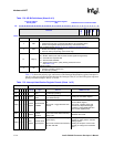
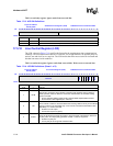
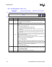
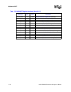
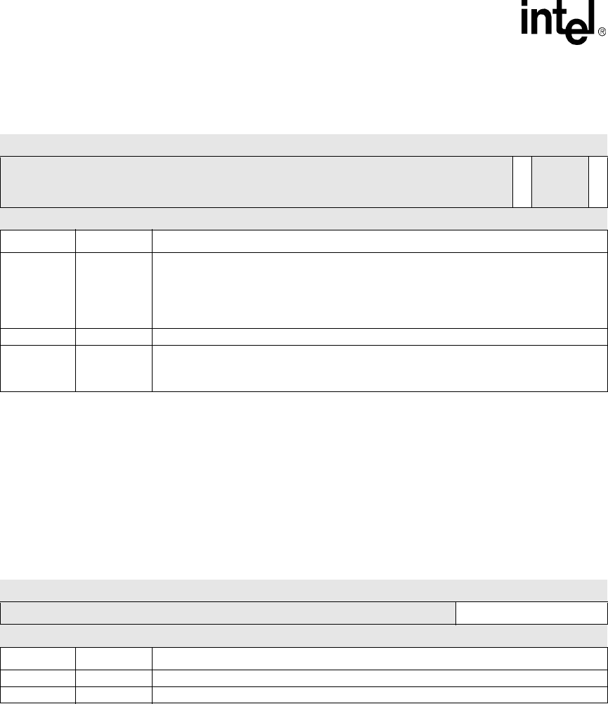
17.5.14 Scratchpad Register (SCR)
The SCR, shown in Table 17-18, has no effect on the UART. It is intended as a scratchpad register
for use by the programmer. It is included for 16550A compatibility.
This is a read-only register. Ignore reads from reserved bits.
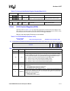
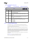
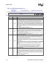
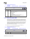
17.5.15 Infrared Selection Register (ISR)
Each UART can manage an IrDA module. The ISR, shown in Table 17-19, controls IrDA functions
(see Section 17.4.5).
This is a read/write register. Ignore reads to reserved bits. Write zeros to reserved bits.
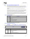
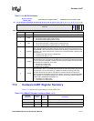
4CTS
CLEAR TO SEND
Complement of the clear to send (nCTS) input. Equivalent to MCR[RTS] if MCR[LOOP] is
set.
0 = nCTS pin is 1
1 = nCTS pin is 0
3:1 — reserved
0 DCTS
DELTA CLEAR TO SEND
0 = No change in nCTS pin since last read of MSR
1 = nCTS pin has changed state
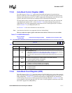
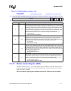
Table 17-17. MSR Bit Definitions (Sheet 2 of 2)
Physical Address
0x4160_0018
Modem Status Register (MSR) PXA255 Processor Hardware UART
Bit
31 30 29 28 27 26 25 24 23 22 21 20 19 18 17 16 15 14 13 12 11 10 9 8 7 6 5 4 3 2 1 0
reserved
CTS
reserved
DCTS
Reset ? ? ? ? ? ? ? ? ? ? ? ? ? ? ? ? ? ? ? ? ? ? ? ? ? ? ? 1 ? ? ? 0
Bits Name Description
Table 17-18. SCR Bit Definitions
Physical Address
0x4160_001C
Scratchpad Register (SCR) PXA255 Processor Hardware UART
Bit
31 30 29 28 27 26 25 24 23 22 21 20 19 18 17 16 15 14 13 12 11 10 9 8 7 6 5 4 3 2 1 0
reserved SCR
Reset
? ? ? ? ? ? ? ? ? ? ? ? ? ? ? ? ? ? ? ? ? ? ? ? 0 0 0 0 0 0 0 0
Bits Name Description
31:8 — reserved
7:0 SCR No effect on UART function