


Intel® PXA255 Processor Developer’s Manual 9-25
I
2
C Bus Interface Unit
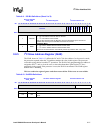
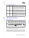
9.9.4 I
2
C Status Register (ISR)
The ISR, shown in Table 9-11, signals I
2
C interrupts to the processor interrupt controller. Software
can use the ISR bits to check the status of the I
2
C unit and bus. ISR bits (bits 9-5) are updated after
the ACK/NAK bit is completed on the I
2
C bus.
The ISR also clears the following interrupts signalled from the I
2
C unit:
• IDBR Receive Full
• IDBR Transmit Empty
• Slave Address Detected
• Bus Error Detected
• STOP Condition Detect
• Arbitration Lost
This is a read/write register. Ignore reads from reserved bits. Write zeros to reserved bits.
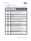
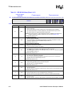
2 ACKNAK
ACK/NAK Control: defines the type of ACK pulse sent by the I
2
C unit when in master-
receive mode.
0 = The I
2
C unit sends an ACK pulse after it receives a data byte.
1 = The I
2
C unit sends a negative ACK (NAK) after it receives a data byte.
The I
2
C unit automatically sends an ACK pulse when it responds to its slave address or
when it responds in slave-receive mode, independent of the ACK/NAK control bit setting.
1STOP
STOP: initiates a STOP condition after the next data byte on the I
2
C bus is transferred in
master mode. In master-receive mode, the ACK/NAK control bit must be set along with this
bit. See Section 9.3.3.3 for more details on the STOP state.
0 = Do not send a STOP.
1 = Send a STOP.
0START
START: initiates a START condition to the I
2
C unit when in master mode. See
Section 9.3.3.1 for more details on the START state.
0 = Do not send a START.
1 = Send a START.
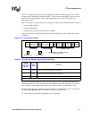
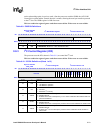
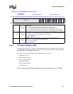
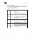
Table 9-10. ICR Bit Definitions (Sheet 3 of 3)
Physical Address
4030_1690
I
2
C Control Register I
2
C Bus Interface Unit
Bit
31 30 29 28 27 26 25 24 23 22 21 20 19 18 17 16 15 14 13 12 11 10 9 8 7 6 5 4 3 2 1 0
reserved
FM
UR
SADIE
ALDIE
SSDIE
BEIE
IRFIE
ITEIE
GCD
IUE
SCLE
MA
TB
ACKNAK
STOP
START
Reset 0 0 0 0 0 0 0 0 0 0 0 0 0 0 0 0 0 0 0 0 0 0 0 0 0 0 0 0 0 0 0