


Intel® PXA255 Processor Developer’s Manual 12-47
USB Device Controller
These are read-only registers. Ignore reads from reserved bits.
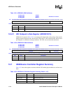
12.6.19 UDC Endpoint x Data Register (UDDR3/8/13)
UDDR3/8/13, shown in Table 12-30, is a double-buffered isochronous IN endpoint that is 256
bytes deep. Data can be loaded via DMA or direct core writes. Because it-is double buffered, up to
two packets of data may be loaded for transmission.
These are write-only registers. Write zeros to reserved bits.
12.6.20 UDC Endpoint x Data Register (UDDR4/9/14)
UDDR4/9/14, shown in Table 12-31, is a double-buffered isochronous OUT endpoint that is 256
bytes deep. The UDC generates an interrupt or DMA request when the EOP is received. Because it
is double-buffered, up to two packets of data may be ready. The data can be removed from the
UDC via DMA or by a direct read from the Megacell. If one packet is being removed and the
packet behind it has already been received, the UDC issues a NAK to the host the next time it sends
an OUT packet to Endpoint(x). This NAK condition remains in place until a full packet space is
available in the UDC at Endpoint(x).
These are read-only registers. Ignore reads from reserved bits.
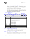
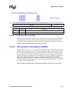
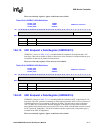
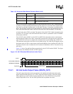
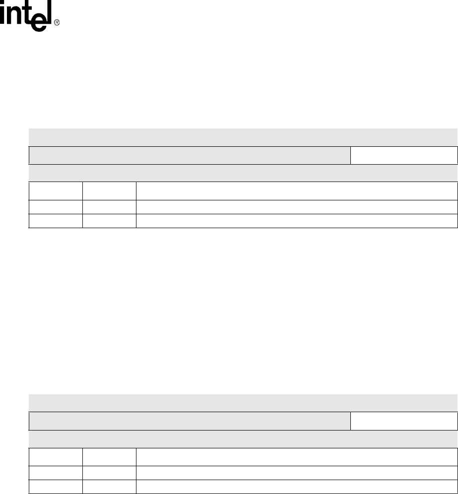
Table 12-29. UDDR2/7/12 Bit Definitions
0x 4060_0180
0x 4060_0680
0x 4060_0B80
UDDR2
UDDR7
UDDR12
USB Device Controller
Bit
31 30 29 28 27 26 25 24 23 22 21 20 19 18 17 16 15 14 13 12 11 10 9 8 7 6 5 4 3 2 1 0
reserved 8-bit Data
Reset
x x x x x x x x x x x x x x x x x x x x x x x x 0 0 0 0 0 0 0 0
Bits Name Description
31:8 — reserved
7:0 DATA Top of endpoint data currently being read
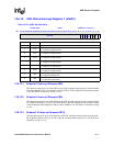
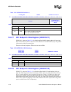
Table 12-30. UDDR3/8/13 Bit Definitions
0x 4060_0200
0x 4060_0700
0x 4060_0C00
UDDR3
UDDR8
UDDR13
USB Device Controller
Bit
31 30 29 28 27 26 25 24 23 22 21 20 19 18 17 16 15 14 13 12 11 10 9 8 7 6 5 4 3 2 1 0
reserved 8-bit Data
Reset
x x x x x x x x x x x x x x x x x x x x x x x x 0 0 0 0 0 0 0 0
Bits Name Description
31:8 — reserved
7:0 DATA Top of endpoint data currently being loaded