


Intel® PXA255 Processor Developer’s Manual 9-3
I
2
C Bus Interface Unit
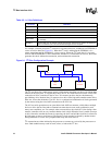
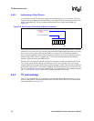
9.3.1 Operational Blocks
The I
2
C unit is connected to the peripheral bus. The processor interrupt mechanism can be used to
notify the CPU that there is activity on the I
2
C bus. Polling can be used instead of interrupts. The
I
2
C unit consists of the two wire interface to the I
2
C bus, an 8-bit buffer for passing data to and
from the processor, a set of control and status registers, and a shift register for parallel/serial
conversions.
The I
2
C unit initiates an interrupt to the processor when a buffer is full, a buffer is empty, the I
2
C
unit slave address is detected, arbitration is lost, or a bus error condition occurs. All interrupt
conditions must be cleared explicitly by software. See Section 9.9.4 for details.
The 8-bit I
2
C Data Buffer Register (IDBR) is loaded with a byte of data from the shift register
interface to the I
2
C bus when receiving data and from the processor internal bus when writing data.
The serial shift register is not user accessible.
The I
2
C Control Register (ICR) and the I
2
C Status Register (ISR) are located in the I
2
C memory-
mapped address space. The registers and their functions are defined in Section 9.9.
The I
2
C unit supports a fast mode operation of 400 Kbits/sec and a standard mode of 100 Kbits/sec.
Refer to The I
2
C-Bus Specification for details.
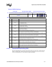
9.3.2 I
2
C Bus Interface Modes
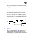
The I
2
C unit can accomplish a transfer in different operation modes. Table 9-3 summarizes the
different modes.
While the I
2
C unit is idle, it defaults to slave-receive mode. This allows the interface to monitor the
bus and receive any slave addresses intended for the processor.
Table 9-3. Modes of Operation
Mode Description
Master - Transmit
•I
2
C unit acts as a master.
• Used for a write operation.
•I
2
C unit sends the data.
•I
2
C unit is responsible for clocking.
• Slave device in slave-receive mode
Master - Receive
•I
2
C unit acts as a master.
• Used for a read operation.
•I
2
C unit receives the data.
•I
2
C unit is responsible for clocking.
• Slave device in slave-transmit mode
Slave - Transmit
•I
2
C unit acts as a slave.
• Used for a master read operation.
•I
2
C unit sends the data.
• Master device in master-receive mode.
Slave - Receive (default)
•I
2
C unit acts as a slave.
• Used for a master write operation.
•I
2
C unit receives the data.
• Master device in master-transmit mode.