


Intel® PXA255 Processor Developer’s Manual 16-21
Network SSP Serial Port
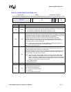
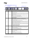
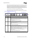
Table 16-4. SSCR1 Bit Definitions (Sheet 1 of 2)
0x04140_0004 SSCR1 Network SSP Serial Port
Bit 31 30 29 28 27 26 25 24 23 22 21 20 19 18 17 16 15 14 13 12 11 10 9 8 7 6 5 4 3 2 1 0
TTELP
TTE
EBCEI
SCFR
reserved
SCLKDIR
SFRMDIR
RWOT
reserved
TSRE
RSRE
TINTE
reserved
STRF
EFWR
RFT TFT
MWDS
SPH
SPO
LBM
TIE
RIE
Reset 0 0 0 0 ? ? 0 0 0 0 0 0 0 ? ? ? 0 0 0 0 0 0 0 0 0 0 0 0 0 0 0 0
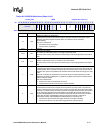
Bits Name Description
31 TTELP
TRANSMIT HI-Z LATER PHASE:
This bit modifies the behavior of TTE. It causes SSPTXD to become Hi-Z 1/2 phase (or one
clock edge) later than normal.
This only occurs with the TI SSP format, and the PSP format if the SSP is a slave to frame.
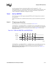
For TI SSP format, this means the SSPTXD is Hi-Z after the rising edge after the LSB (The
LSB is present a full clock).
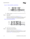
For PSP format if the SSP is a slave to frame, this means the SSPTXD is Hi-Z two clock
edges after the LSB (the LSB is present a full clock).
If SSPSCLK is an input, the device driving SSPSCLK must provide another clock edge.
0 – SSPTXD Hi-Z timing is as described below for TTE.
1 – SSPTXD Hi-Z timing is extended by 1/2 phase. Only valid for TI SSP, and PSP if the
SSP is a slave to frame.
30 TTE
TRANSMIT HI-Z ENABLE:
This bit controls whether or not SSPTXD is driven or Hi-Z when the SSP is idle.
For Microwire* SSPTXD is driven at the same clock edge that the MSB is driven, and
SSPTXD is Hi-Z after the next rising edge of SSPSCLK for the LSB (1 clock edge after the
clock edge that starts the LSB).
For SPI, SSPTXD is Hi-Z whenever SSPFRM is deasserted.
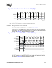
For TI SSP format, SSPTXD is driven with the MSB at the first rising edge of SSPSCLK after
SSPSFRM is asserted and is Hi-Z after the falling edge of SSPSCLK for the LSB (1 clock
edge after the clock edge that starts the LSB).
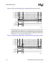
For PSP format, if the SSP is a slave to frame SSPTXD is Hi-Z on the same clock edge that
starts the LSB.
For PSP format if the SSP is a master to frame, SSPTXD is Hi-Z on the clock
edge after the clock edge for the LSB. This occurs even if the SSP is a master of clock and
this clock edge does not appear on SSPSCLK.
0 – SSPTXD line is driven when SSP is idle
1 – SSPTXD line is Hi-Z when SSP is idle
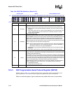
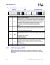
29 EBCEI
BIT COUNT ERROR INTERRUPT MASK:
Disables bit count error interrupts. SSSR will still indicate an error. A bit count error occurs
when the SSP is a slave to clock or frame and the SSP detects a new frame before the
internal bit counter has reached 0.
0 – Bit count error events will generate an interrupt.
1 – Bit count error events will not generate an interrupt.
28 SCFR
SLAVE CLOCK FREE RUNNING:
SCFR in slave mode (SCLKDIR set) must be cleared if the input clock from the external
source is running continuously.
In master mode (SCLKDIR cleared) this bit is ignored.
Master mode only:
0 – Clock input to SSPSCLK is continuously running
1 – Clock input to SSPSCLK is active only during transfers.
27:26 — reserved