


Intel® PXA255 Processor Developer’s Manual 16-7
Network SSP Serial Port
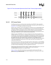
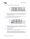
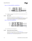
Note: When configured as either master or slave (to clock or frame) the SSP continues to drive SSPTXD
with the last bit of data sent (the LSB). If SSCR0[SSE] is cleared, SSPTXD goes low. The state of
SSPRXD is undefined before the MSB and after the LSB is transmitted. For minimum power
consumption, this pin must not float.
Note: The phase and polarity of SSPSCLK can be configured for four different modes. This example
shows just one of those modes (SSCR1[SPO] = 0, SSCR1[SPH] = 0).
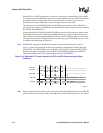
Note: When configured as either master or slave (to clock or frame) the SSP continues to drive SSPTXD
with the last bit of data sent (the LSB). If SSCR0[SSE] is cleared, SSPTXD goes low. The state of
SSPRXD is undefined before the MSB and after the LSB is transmitted. For minimum power
consumption, this pin must not float.
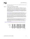
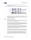
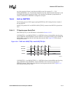
16.4.3.2.1 Serial Clock Phase (SPH)
The phase relationship between the SSPSCLK and the serial frame (SSPSFRM) pins when the
Motorola SPI* protocol is selected is controlled by SSCR1[SPH].
When SPH is cleared, SSPSCLK remains in its inactive or idle state (as determined by
SSCR1[SPO]) for one full cycle after SSPSFRM is asserted low at the beginning of a frame.
SSPSCLK continues to transition for the rest of the frame. It is then held in its inactive state for
one-half of an SSPSCLK period before SSPSFRM is de-asserted high at the end of the frame.
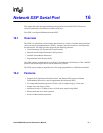
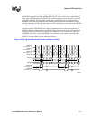
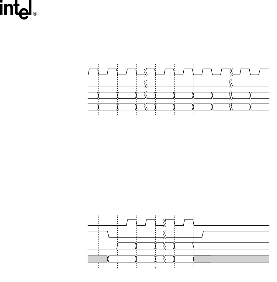
Figure 16-3. Motorola SPI* Frame Protocol (multiple transfers)
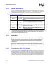
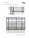
Figure 16-4. Motorola SPI* Frame Protocol (single transfers)
A9651-01
SSPSCLK
SSPSFRM
Bit[N]
Bit[N-1] Bit[0]
Bit[N]
Bit[N-1] Bit[1] Bit[0]
Bit[0]
SSPTX
SSPRX
Bit[1] Bit[0]
Bit[N]
Bit[N-1] Bit[0]
Bit[N]
Bit[N-1] Bit[1] Bit[0]
Bit[0]
Bit[1] Bit[0]
A9519-02
SSPRXD
SSPSFRM
SSPSCLK
SSPTXD
MSB LSB
Bit[N]Undefined Undefined
End of Transfer Data State
Bit[N-1] Bit[1] Bit[0]
Bit[N] Bit[N-1] Bit[1] Bit[0]
4 to 32 Bits