


Intel® PXA255 Processor Developer’s Manual 15-1
MultiMediaCard Controller 15
15.1 Overview
The PXA255 processor MultiMediaCard (MMC) controller acts as a link between the software
used to access the processor and the MMC stack (a set of memory cards). The MMC controller is
designed to support the MMC system, a low-cost data storage and communications system. A
detailed description of the MMC system is available through the MMC Association’s web site at
www.mmca.org. The processor’s MMC controller is based on the standards outlined in The
MultiMediaCard System Specification Version 2.1 with the exception that one- and three-byte data
transfers are not supported and the maximum block length is 1023.
The MMC controller supports the translation protocol from a standard MMC or Serial Peripheral
Interface (SPI) bus to the MMC stack. The software used to access the processor must indicate
whether to use MMC or SPI mode as the protocol to communicate with the MMC controller.
The MMC controller features:
• Data transfer rates up to 20 Mbps
• A response FIFO
• Dual receive data FIFOs
• Dual transmit FIFOs
• Support for two MMCs in either MMC or SPI mode
The MMC controller contains all card-specific functions, serves as the bus master for the MMC
system, and implements the standard interface to the card stack. The controller handles card
initialization; CRC generation and validation; and command, response, and data transactions.
The MMC controller is a slave to the software and consists of command and control registers, a
response FIFO, and data FIFOs. The software has access to these registers and FIFOs and
generates commands, interprets responses, and controls subsequent actions.
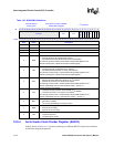
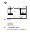
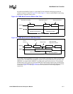
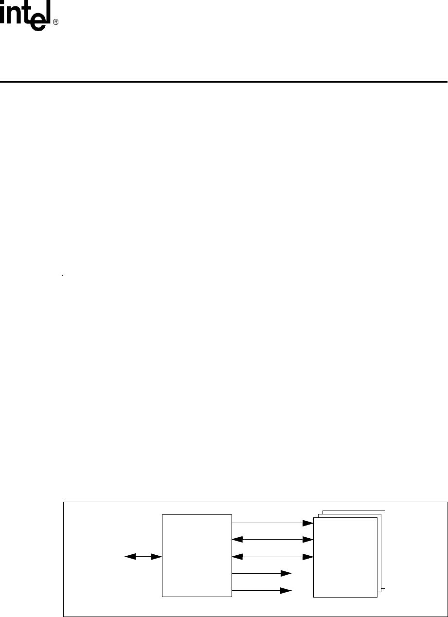
Figure 15-1 shows a block diagram of the interaction of a typical MMC stack, the MMC controller,
and a software.
Figure 15-1. MMC System Interaction
MMCCS1
MMCCS0
Software
Interface
MMCLK
MMCMD
MMDAT
MMC
Stack
MMCCS0 and MMCCS1 are only used in SPI mode.
MMC
Controller
Processor’s