


4-30 Intel® PXA255 Processor Developer’s Manual
System Integration Unit
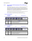
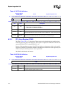
4.3.2.2 RTC Alarm Register (RTAR)
The RTAR, Table 4-38, is a 32-bit register. The processor can both read and write to this register.
Following each rising edge of the HZ clock, this register is compared to the RCNR. If the two are
equal and RTSR[ALE] is set, then RTSR[AL] is set.
Because of the asynchronous nature of the HZ clock relative to the processor clock, writes to this
register are controlled by a hardware mechanism that delays the actual write to the register by two
32 kHz clock cycles after the processor store is performed.
The RTAR is initialized to 0x0 at reset.
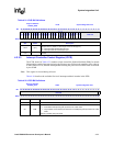
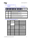
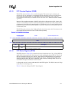
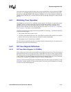
Table 4-37. RTTR Bit Definitions
Physical Address
0x4090_000C
RTTR System Integration Unit
Bit
31 30 29 28 27 26 25 24 23 22 21 20 19 18 17 16 15 14 13 12 11 10 9 8 7 6 5 4 3 2 1 0
LCK
reserved DEL CK_DIV
Reset
0 ? ? ? ? ? 0 0 0 0 0 0 0 0 0 0 0 1 1 1 1 1 1 1 1 1 1 1 1 1 1 1
Bits Name Description
<31> LCK
Locking bit for the trim value.
0 – RTTR value is allowed to be altered.
1 – RTTR value is not allowed to be altered.
<30:26> — reserved
<25:16> DEL
Trim delete count.
This value represents the number of 32 kHz clocks to delete when clock trimming begins.
<15:0> CK_DIV
Clock divider count.
This value is the number of 32 kHz clock cycles, plus 1, per HZ clock cycle.
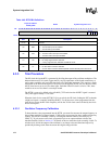
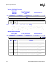
Table 4-38. RTAR Bit Definitions
Physical Address
0x4090_0004
RTAR System Integration Unit
Bit
31 30 29 28 27 26 25 24 23 22 21 20 19 18 17 16 15 14 13 12 11 10 9 8 7 6 5 4 3 2 1 0
RTMV
Reset
0 0 0 0 0 0 0 0 0 0 0 0 0 0 0 0 0 0 0 0 0 0 0 0 0 0 0 0 0 0 0 0
Bits Name Description
<31:0> RTMV
RTC Target Match Value.
The value compared against the RTC counter.