Intel® PXA255 Processor Developer’s Manual 5-3
DMA Controller
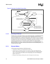
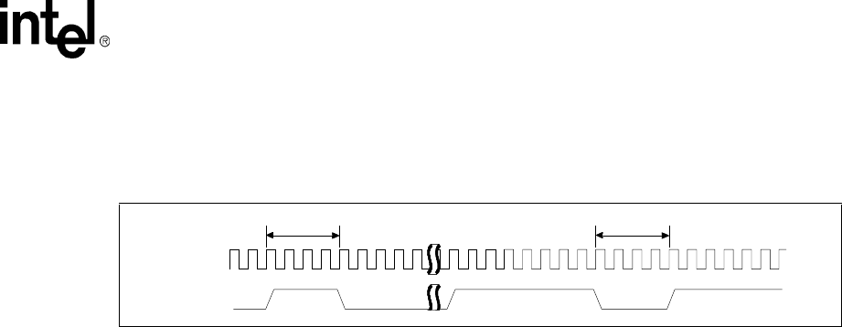
must remain deasserted for at least four MEMCLKs. The DMAC registers the transition from 0 to
1 to identify a new request. The external companion chip must not assert another DREQ until the
previous DMA data transfer starts.
The PREQ[37:0] bits are the active high internal signals from the on-chip peripherals. Unlike
DREQ[1:0], they are level sensitive. The DMAC does not sample the PREQ[37:0] signals until it
completely finishes the current data transfer. For a write request to the on-chip peripheral, the
DMAC begins to sample the PREQ[37:0] signals after it sends the last byte of the write request.
For a read request, the DMAC begins to sample the PREQ[37:0] signals after it sends the last byte
that pertains to the read on the internal bus.
The DCSR[REQPEND] bit indicates the status of the pending request for the channel.
If a DREQx assertion sets the DCSR[REQPEND] bit and software resets the DCSR[RUN] bit to
stop the channel, the DCSR[REQPEND] bit and the internal registers that hold the DREQx
assertion information may remain set even though the channel has stopped. To reset the
DCSR[REQPEND] bit, software must send a dummy descriptor that transfers some data.
5.1.2.2 DMA_IRQ Signal
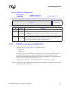
The processor has 16 IRQ signals, one for each DMA channel. Each DMA IRQ can be read in the
DINT register that is shown in Table 5-6. The user can mask some bits that cause interrupts on a
channel, such as ENDIRQEN, STARTIRQEN, and STOPIRQEN.
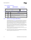
When DMA interrupt occurs, it is visible in Pending Interrupt Register Bit 25 (see Section 4.2.2.5,
“Interrupt Controller Pending Register (ICPR)” on page 4-25). When a pending interrupt becomes
active, it is sent to the CPU if its corresponding ICMR mask Bit 25 (see Section 4.2.2.1, “Interrupt
Controller Mask Register (ICMR)” on page 4-22) is set to a one.
5.1.3 DMA Channel Priority Scheme
The DMA channel priority scheme allows peripherals that require high bandwidth to be serviced
more often than those requiring less bandwidth. The DMA channels are internally divided into four
sets. Each set contains four channels. The channels get a round-robin priority in each set. Set zero
has the highest priority. Set 1 has higher priority than sets two and three. Sets two and three are low
priority sets. Refer to Table 5-2 for details. High bandwidth peripherals must be programmed in set
zero. Memory-to-memory moves and low bandwidth peripherals must be programmed in set two
or three. When all channels are running concurrently, set zero is serviced four times out of any
eight consecutive channel servicing instances. Set one is serviced twice and sets two and three are
each serviced once.
If two or more channels are active and request a DMA, the priority scheme in Table 5-2 applies.
Request priority does not affect requests that have already started. The DMAC priority scheme is
considered when the smaller dimension of the DCMDx[SIZE] or DCMDx[LENGTH] is complete.
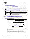
Figure 5-2. DREQ timing requirements
dreq_deassert_mindreq_deassert_mindreq_assert_mindreq_assert_min
mem_clk
DREQ


