


13-2 Intel® PXA255 Processor Developer’s Manual
AC’97 Controller Unit
13.3 Signal Description
The AC’97 signals form the AC-link, which is a point-to-point synchronous serial interconnect that
supports full-duplex data transfers. All digital audio streams, Modem line CODEC streams, and
command/status information are communicated over the AC-link. The AC-link uses General
Purpose I/Os (GPIOs). Software must reconfigure the GPIOs to use them as the AC-link. The AC-
link pins are listed and described in Table 13-1.
13.3.1 Signal Configuration Steps
1. Configure SYNC and SDATA_OUT as outputs.
2. Configure BITCLK, SDATA_IN_0, and SDATA_IN_1 as inputs.
3. nACRESET is a dedicated output. It remains asserted on power-up. Complete these steps to
deassert nACRESET:
a. Configure the other AC’97 signals as previously described.
b. In the Global Control Register (GCR), Set the GCR[COLD_RST] bit. Refer to Table 13-7
for more details.
Note: Refer to Section 4.1.3, “GPIO Register Definitions” on page 4-6 for details on programing the
GPDR and GAFR for use with the ACUNIT.
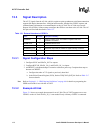
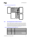
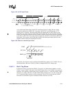
13.3.2 Example AC-link
Figure 13-1 shows an example interconnect for an AC-link. The ACUNIT supports one or two
CODECs on the AC-link. SDATA_IN_1 is not needed if only a Primary CODEC is connected.
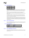
Table 13-1. External Interface to CODECs
Name Direction Description summary
nACRESET O
Active-low CODEC reset. The CODEC’s registers reset when
nACRESET is asserted.
GP28/BITCLK I 12.288 MHz bit-rate clock.
GP31/SYNC O 48 kHz frame indicator and synchronizer.
GP30/SDATA_OUT O Serial audio output data to CODEC for digital-to-analog conversion.
GP29/SDATA_IN_0 I Serial audio input data from Primary CODEC.
GP32/SDATA_IN_1 I Serial audio input data from Secondary CODEC.