


6-2 Intel® PXA255 Processor Developer’s Manual
Memory Controller
6.2 Functional Description
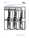
The processor has three different memory spaces: SDRAM, Static Memory, and Card Memory.
SDRAM has four partitions, Static Memory has six, and Card space has two. When memory access
attempts to burst across the boundary between adjacent partitions, ensure that the configurations
for the partitions are identical. The configurations must be identical in every aspect, including
external bus width and burst length.
6.2.1 SDRAM Interface Overview
The processor supports the SDRAM interface, which supports four 16- and 32-bit-wide SDRAM
partitions. Each partition is allocated 64 Mbytes of the internal memory map, but the actual size of
each partition depends on the SDRAM configuration. The four partitions are divided into two
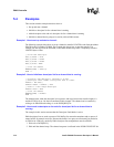
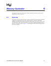
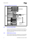
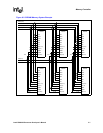
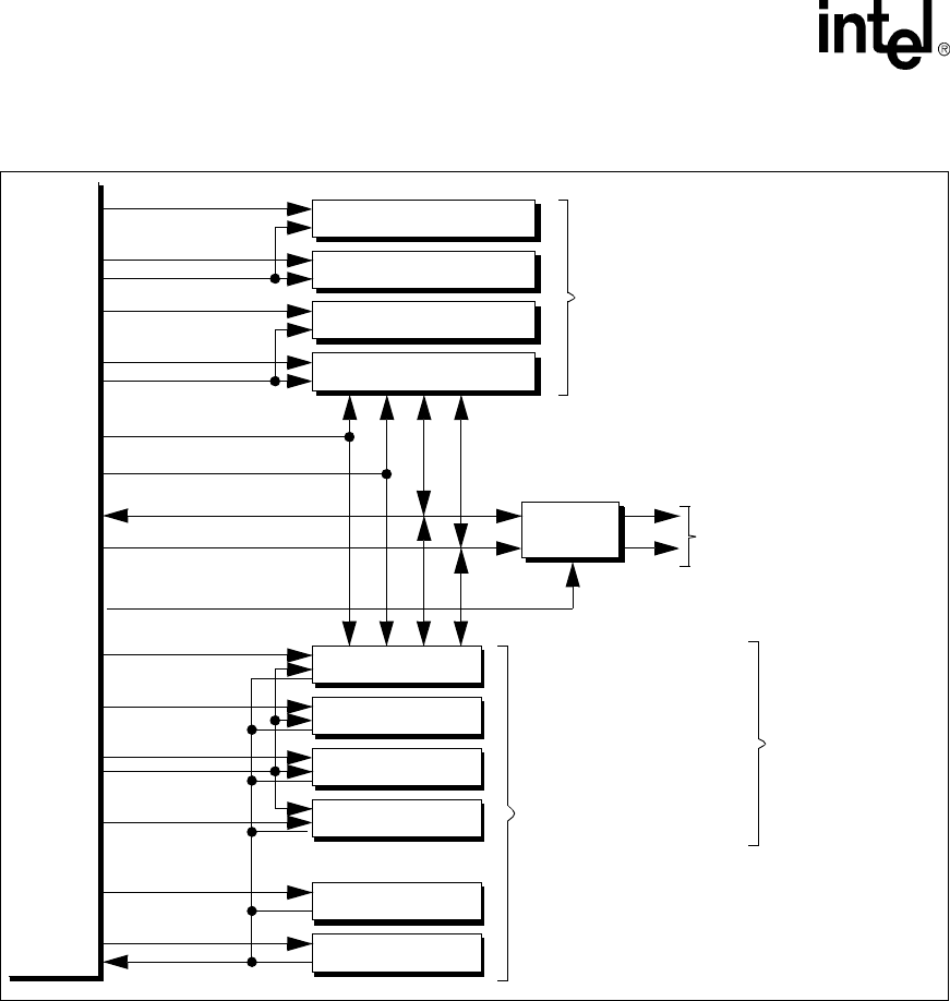
Figure 6-1. General Memory Interface Configuration
Memory
Controller
Interface
SDRAM Partition 0
SDRAM Partition 1
SDRAM Partition 2
SDRAM Partition 3
nSDCS<0>
nSDCS<1>
nSDCS<2>
nSDCS<3>
nCS<0>
nCS<1>
nCS<2>
nCS<3>
nCS<4>
nCS<5>
Static Bank 3
Static Bank 4
Static Bank 5
Buffers and
Transceivers
DQM[3:0]
nSDRAS, nSDCAS
SDCLK<2>, SDCKE<1>
SDCLK<1>, SDCKE<1>
SDCLK<0>,
MD[31:0]
MA[25:0]
Card Control
RDY
SDRAM Memory Interface
Up to 4 partitions of SDRAM
memory (16- or 32-bit wide)
16-bit PC Card Memory Interface
Up to 2-socket support.
Requires some
external buffering
Synchronous Static Memory Interface
Up to 6 banks of ROM, Flash,
NOTE:
Static Bank 0 must be populated by
Static Memory or
Variable Latency I/O Interface
(16 or 32-bit wide)
(16 or 32-bit wide)
SRAM, Variable Latency I/O,
“bootable” memory
Static Bank 0
Static Bank 1
Static Bank 2
SDCKE<0>
Up to 4 banks of synchronous
static memory (nCS[3:0]).
NOTE:
Static Bank 0 must be populated by
“bootable” memory
MD[15:0]
MA[24:10]