


17-22 Intel® PXA255 Processor Developer’s Manual
Hardware UART
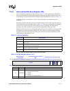
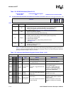
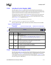
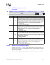
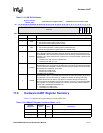
Table 17-16. MCR Bit Definitions (Sheet 1 of 2)
Physical Address
0x4160_0010
Modem Control Register (MCR) PXA255 Processor Hardware UART
Bit
31 30 29 28 27 26 25 24 23 22 21 20 19 18 17 16 15 14 13 12 11 10 9 8 7 6 5 4 3 2 1 0
reserved
AFE
LOOP
OUT2
reserved
RTS
reserved
Reset ? ? ? ? ? ? ? ? ? ? ? ? ? ? ? ? ? ? ? ? ? ? ? ? ? ? 0 0 0 ? 0 ?
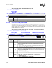
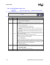
Bits Name Description
31:8 — reserved
5AFE
AUTOFLOW CONTROL ENABLE
0 = Auto-RTS and auto-CTS are disabled.
1 = Auto-CTS is enabled. If MCR[RTS] is also set, both auto-CTS and auto-RTS is
enabled.
4 LOOP
LOOPBACK MODE
This bit provides a local loopback feature for diagnostic testing of the UART. When LOOP is
set to a logic 1, the following occurs:
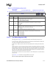
• The transmitter serial output is set to a logic 1 state.
• The receiver serial input is disconnected from the pin.
• The output of the Transmitter Shift register is “looped back” into the Receiver Shift
register input.
• The four modem control inputs (nCTS, nDSR, nDCD, and nRI) are disconnected from
the pins and the modem control output pins (nRTS and nDTR) are forced to their
inactive state.
Coming out of the loopback mode may result in unpredictable activation of the delta bits
(bits 3:0) in the Modem Status register (MSR). It is recommended that MSR is read once to
clear the delta bits in the MSR.
Loopback mode must be configured before the UART is enabled.
MCR[RTS] is connected to the Modem Status register CTS bit: This allows software to test
CTS functionality by setting or clearing MCR[RTS]
• RTS = 1 forces CTS to 1
• RTS = 0 forces CTS to a 0
In loopback mode, data that is transmitted is immediately received. This feature lets the
processor verify the transmit and receive data paths of the UART. The transmit, receive and
modem control interrupts are operational, except the modem control interrupts are activated
by MCR bits, not the modem control pins. A break signal can also be transferred from the
transmitter section to the receiver section in loopback mode.
0 = Normal UART operation
1 = Loopback mode UART operation
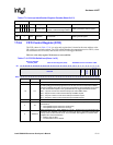
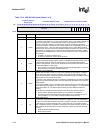
3OUT2
OUT2 SIGNAL CONTROL
OUT2 connects the UART’s interrupt output to the interrupt controller unit. When LOOP=0:
0 = UART interrupt is disabled
1 = UART interrupt is enabled.
When LOOP=1, interrupts always go to the processor.
2 — reserved