


Intel® PXA255 Processor Developer’s Manual 10-7
UARTs
10.4.2.2 Transmit Holding Register (THR)
In non-FIFO mode, the THR, shown in Table 10-4, holds the data byte that is to be transmitted
next. When the TSR is emptied, the contents of the THR are loaded in the TSR and the
LSR[TDRQ] is set to a 1.
In FIFO mode, a write to the THR puts data into the top of the FIFO. The data at the front of the
FIFO is loaded to the TSR when that register is empty.
This is a write-only register. Write zeros to reserved bits.
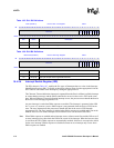
10.4.2.3 Divisor Latch Registers (DLL and DLH)
Each UART contains a programmable baud rate generator that can take the 14.7456 MHz fixed
input clock and divide it by 1 to (2
16
–1). For the FFUART and the STUART, the divisor is from 4
to (2
16
–1). The baud rate generator output frequency is 16 times the baud rate. Two 8-bit latch
registers, shown in Table 10-5 and Table 10-6, store the divisor in a 16-bit binary format. Load
these divisor latches during initialization to ensure that the baud rate generator operates properly. If
each Divisor Latch is loaded with a 0, the 16X clock stops. The Divisor Latches are accessed with
a word write.
The baud rate of the data shifted in to or out of a UART is given by the formula:
For example: if the divisor is 24, the baud rate is 38400 bps.
The divisor’s reset value is 0x0002. For the FFUART and the STUART, the divisor must be set to
at least 0x0004 before the UART unit is enabled.
These are read/write registers. Ignore reads from reserved bits. Write zeros to reserved bits.
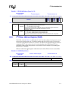
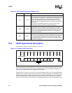
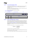
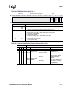
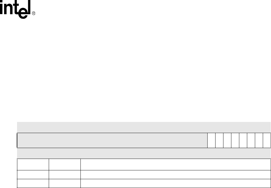
Table 10-4. THR Bit Definitions
Base (DLAB=0) Transmit Holding Register UART
Bit
31 30 29 28 27 26 25 24 23 22 21 20 19 18 17 16 15 14 13 12 11 10 9 8 7 6 5 4 3 2 1 0
reserved
THR7
THR6
THR5
THR4
THR3
THR2
THR1
THR0
Reset 0 0 0 0 0 0 0 0 0 0 0 0 0 0 0 0 0 0 0 0 0 0 0 0 0 0 0 0 0 0 0 0
Bits Name Description
31:8 — reserved
7:0 THR[7:0] Data byte transmitted least significant bit first.
BaudRate
14.7456 MHz
16xDivisor()
----------------------------------=