


13-12 Intel® PXA255 Processor Developer’s Manual
AC’97 Controller Unit
The ACUNIT only supports a 16-bit resolution from the microphone.
13.4.2.8 Slots 7-11: Reserved
Slots 7-11 are reserved for future use. The ACUINT ignores them.
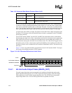
13.4.2.9 Slot 12: I/O Status
GPIOs which are configured as inputs return their status in Slot 12 of every frame. Only the 16
MSBs are used to return GPIO status. Bit 0 in the LSBs indicates a GPI Input Interrupt event. See
the AC’97 revision 2.0 spec for more information.
The data returned on the latest frame is also accessible to software through the CODEC register at
address 0x54 in the modem CODEC I/O space. Data received in Slot 12 is stored internally in the
ACUNIT. So when software initiates a read of the CODEC register at address 0x54 in the modem
CODEC I/O space, the read data is already inside the ACUNIT.
13.5 AC-link Low Power Mode
Software must set the ACLINK_OFF bit of the GCR to one before the processor enters Sleep
Mode. The ACUNIT then drives SYNC and SDATA_OUT to a logic low level . The ACUNIT
maintains nACRESET high when ACLINK_OFF is set to one.
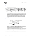
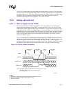
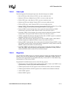
13.5.1 Powering Down the AC-link
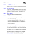
The AC-link signals enter a low power mode after the PR4 bit of the AC’97 CODEC Powerdown
Register (0x26) is set to a 1 (by writing 0x1000). Then, the Primary CODEC drives both BITCLK
and SDATA_IN to a logic low voltage level. The sequence follows the timing diagram shown in
Figure 13-7.
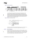
Figure 13-7. AC-link Powerdown Timing
SDATA_OUT
TAG
SYNC
BITCLK
Write to
0x26
Data
PR4
slot 12
prev. frame
TAG
slot 12
prev. frame
SDATA_IN
Note: BITCLK not to scale