


Intel® PXA255 Processor Developer’s Manual 7-23
LCD Controller
Color/Monochrome Select (CMS) — selects whether the LCD controller operates in color or
monochrome mode. When CMS=0, color mode is selected. Palette entries are 16 bits wide (5-bits
red, 6-bits green, 5-bits blue), 8 data pins are enabled for single-panel mode, 16 data pins are
enabled for dual-panel mode, and all three dither blocks are used, one each for the red, green, and
blue pixel components. When CMS=1, monochrome mode is selected, palette entries are 8 bits
wide, 4 or 8 data pins are enabled for single-panel mode, 8 data pins are enabled for dual-panel
mode, and the blue dither block is used.
LCD Enable (ENB) — used to enable and quickly disable all LCD controller operation. When
ENB=0, the LCD controller is either disabled or in the process of quickly disabling, and all of the
LCD pins can be used for GPIO. When ENB=1, the LCD controller is enabled.
All other control registers must be initialized before setting ENB. LCCR0 can be programmed last,
and all bit fields can be configured at the same time with a word write to the register. If ENB is
cleared while the LCD controller is enabled, the LCD controller will immediately stop requesting
data from the LCD DMAC, and the current frame will not complete. The LCD controller must not
be re-enabled until the QD status flag is set in register LCSR, indicating the quick disable is
complete. Quick disable is for sleep shutdown. Regular shutdown of the LCD controller at the end
of the frame can be done via the LCD Disable bit, LCCR0[DIS]. There are separate maskable
interrupts for quick disable and regular disable. See Section 7.2.1 for more information.
This is a read/write register. Ignore reads from reserved bits. Write zeros to reserved bits.
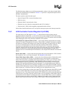
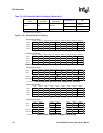
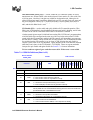
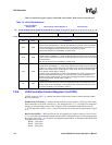
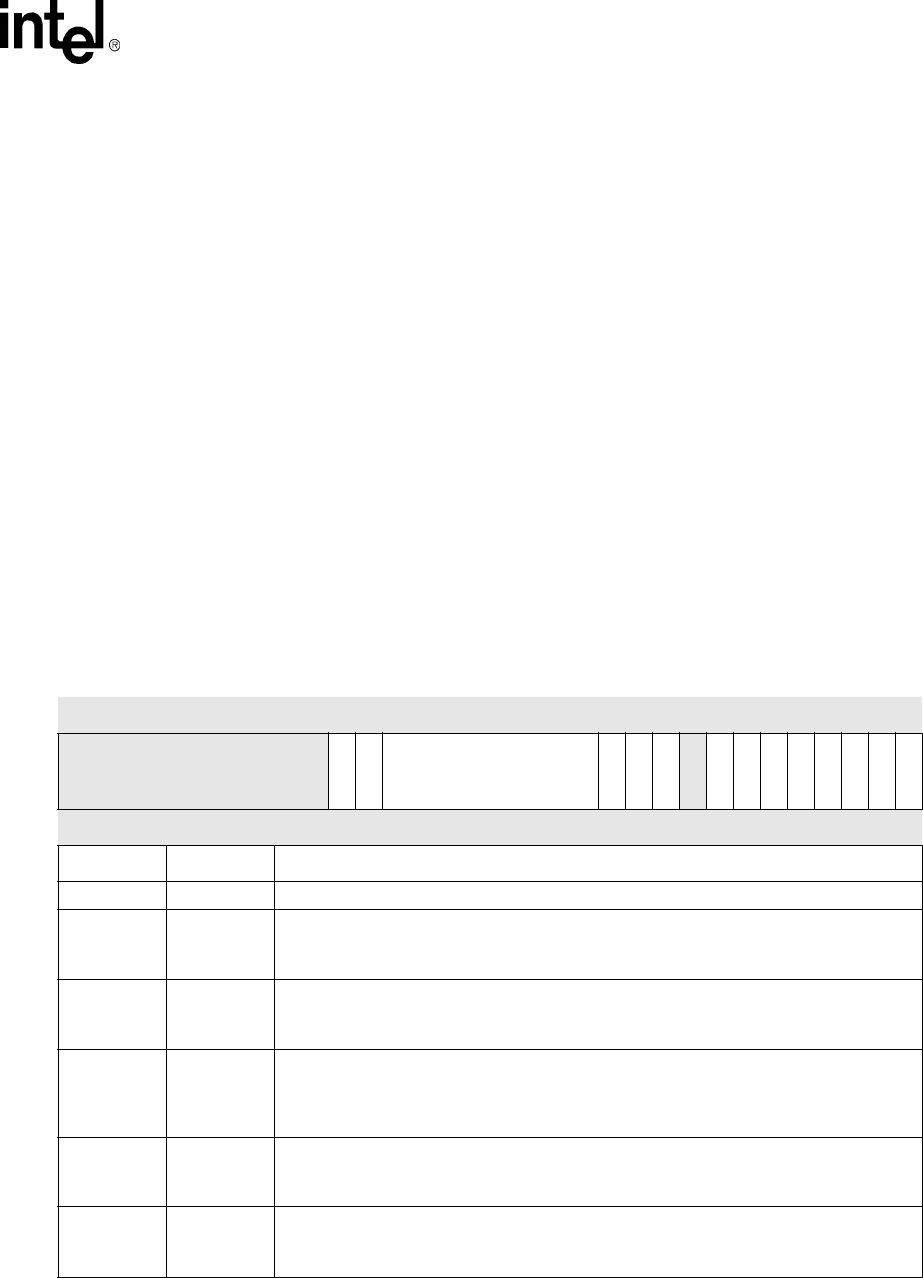
Table 7-3. LCCR0 Bit Definitions (Sheet 1 of 2)
Physical Address
0x4400_0000
LCCR0 LCD Controller
Bit
31 30 29 28 27 26 25 24 23 22 21 20 19 18 17 16 15 14 13 12 11 10 9 8 7 6 5 4 3 2 1 0
reserved
OUM
BM
PDD
QDM
DIS
DPD
reserved
PAS
EFM
IUM
SFM
LDM
SDS
CMS
ENB
Reset X X X X X X X X X X X X 0 0 0 0 0 0 0 0 0 0 0 0 0 0 0 0 0 0 0 0
Bits Name Description
31:22 — reserved
21 OUM
Output FIFO Underrun mask:
0 = FIFO underrun errors generate an interrupt.
1 = FIFO underrun errors do not generate an interrupt.
20 BM
Branch Mask:
0 = Generates an interrupt after branching to a new frame.
1 = Branch Start (BS) condition does not generate an interrupt.
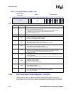
19:12 PDD
Palette DMA Request Delay:
Value (0–255) specifies the number of internal bus clocks to wait before requesting another
burst of palette data. The counter starts decrementing when the first word is written to the
input FIFO buffer. PDD = 0x00 disables this function.
11 QDM
LCD Quick Disable Mask:
0 = Generate an interrupt after quick disable.
1 = Quick Disable (QD) status does not generate an interrupt.
10 DIS
LCD Disable:
0 = LCD Controller has not been disabled.
1 = LCD Controller has been disabled, or is in the process of disabling.