


12-48 Intel® PXA255 Processor Developer’s Manual
USB Device Controller
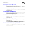
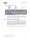
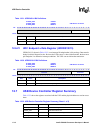
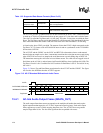
12.6.21 UDC Endpoint x Data Register (UDDR5/10/15)
UDDR5/10/15, shown in Table 12-32, is an interrupt IN endpoint that is 8 bytes deep. Data must be
loaded via direct Megacell writes. Because the USB system is a host initiator model, the host must
poll Endpoint 5 to determine interrupt conditions. The UDC can not initiate the transaction.
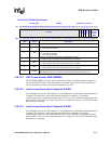
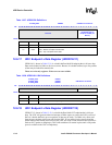
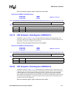
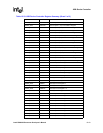
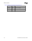
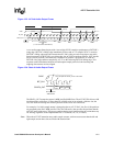
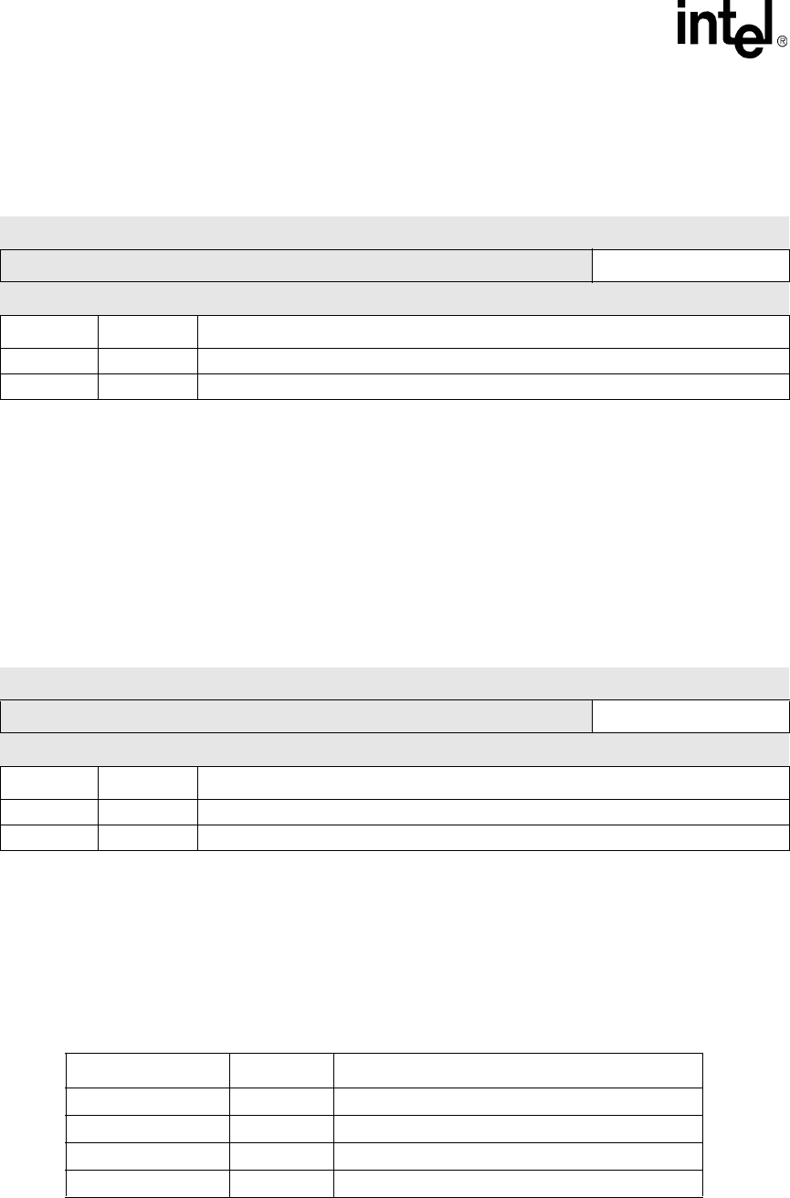
12.7 USB Device Controller Register Summary
Table 12-33 shows the registers associated with the UDC and the physical addresses used to access
them.
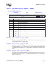
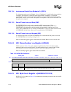
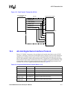
Table 12-31. UDDR4/9/14 Bit Definitions
0x 4060_0400
0x 4060_0900
0x 4060_0E00
UDDR4
UDDR9
UDDR14
USB Device Controller
Bit
31 30 29 28 27 26 25 24 23 22 21 20 19 18 17 16 15 14 13 12 11 10 9 8 7 6 5 4 3 2 1 0
reserved 8-bit Data
Reset x x x x x x x x x x x x x x x x x x x x x x x x 0 0 0 0 0 0 0 0
Bits Name Description
31:8 — reserved
7:0 DATA Top of endpoint data currently being loaded
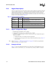
Table 12-32. UDDR5/10/15 Bit Definitions
0x 4060_00A0
0x 4060_00C0
0x 4060_00E0
UDDR5
UDDR10
UDDR15
USB Device Controller
Bit
31 30 29 28 27 26 25 24 23 22 21 20 19 18 17 16 15 14 13 12 11 10 9 8 7 6 5 4 3 2 1 0
reserved 8-bit Data
Reset
x x x x x x x x x x x x x x x x x x x x x x x x 0 0 0 0 0 0 0 0
Bits Name Description
31:8 — reserved
7:0 DATA Top of endpoint data currently being loaded
Table 12-33. USB Device Controller Register Summary (Sheet 1 of 3)
Address Name Description
0x4060_0000 UDCCR UDC Control Register
0x4060_0004 — reserved for future use
0x4060_0008 UDCCFR UDC Control Function Register
0x4060_000C — reserved for future use