


Intel® PXA255 Processor Developer’s Manual 14-3
Inter-Integrated-Circuit Sound (I2S) Controller
2. Program SYSUNIT’s GPIO Alternate Function Select Register (GAFR). See Section 4.1.3.6,
“GPIO Alternate Function Register (GAFR0_L, GAFR0_U, GAFR1_L, GAFR1_U,
GAFR2_L, GAFR2_U)” on page 4-16 for details regarding the GAFR.
To configure SYNC and SDATA_OUT as outputs, follow these steps:
1. Program SYSUNIT’s GPIO Direction Register (GPDR). See Section 4.1.3.2, “GPIO Pin
Direction Registers (GPDR0, GPDR1, GPDR2)” on page 4-8 for details regarding the GPDR.
2. Program SYSUNIT’s GPIO Alternate Function Select Register (GAFR). See Section 4.1.3.6,
“GPIO Alternate Function Register (GAFR0_L, GAFR0_U, GAFR1_L, GAFR1_U,
GAFR2_L, GAFR2_U)” on page 4-16 for details regarding the GAFR.
To configure SDATA_IN as an input, follow these steps:
1. Program SYSUNIT’s GPIO Direction Register (GPDR). See Section 4.1.3.2, “GPIO Pin
Direction Registers (GPDR0, GPDR1, GPDR2)” on page 4-8 for details regarding the GPDR.
2. Program SYSUNIT’s GPIO Alternate Function Select Register (GAFR). See Section 4.1.3.6,
“GPIO Alternate Function Register (GAFR0_L, GAFR0_U, GAFR1_L, GAFR1_U,
GAFR2_L, GAFR2_U)” on page 4-16 for details regarding the GAFR.
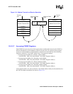
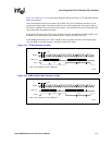
14.3 Controller Operation
The I
2
S Controller (I2SC) can be accessed either by the processor or by the DMA controller.
The processor uses programmed I/O instructions to access the I2SC and can access the following
types of data:
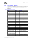
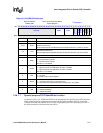
• I2SC registers data — All registers are 32 bits wide and are aligned to word boundaries. See
Section 14.6 for further details.
• I2SC FIFO data — An entry is placed into the Transmit FIFO by writing to the I2SC’s Serial
Audio Data register (SADR). Writing to SADR updates a Transmit FIFO entry. Reading
SADR flushes out a Receive FIFO entry.
• I
2
S CODEC data — The CODEC registers can be accessed through the L3 bus. The L3 bus
operation is emulated by software controlling 3 GPIO pins.
The DMA controller can only access the FIFOs. Accesses are made through the SADR, as
explained in the previous paragraph. The DMA controller accesses FIFO data in blocks of 8, 16, or
32 bytes. The DMA controller responds to the following DMA requests made by the I2SC:
• The Transmit FIFO request is based on the transmit threshold (TFTH) setting and is asserted if
the Transmit FIFO has less than TFTH+1 entries. See Table 14-3 for further details regarding
TFTH.
• The Receive FIFO request is based on the receive threshold (RFTH) setting and is asserted if
the Receive FIFO has RFTH+1 or more entries. See Table 14-3 for further details regarding
RFTH.
14.3.1 Initialization
1. Set the BITCLK direction by programming the SYSUNIT’s GPIO Direction register, the
SYSUNIT’s GPIO Alternate Function Select register, and bit 2 of the I2SC’s Serial Audio
Controller Global Control Register (SACR0).