


15-2 Intel® PXA255 Processor Developer’s Manual
MultiMediaCard Controller
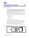
The MMC bus connects the card stack to the controller. The software and controller can turn the
MMC clock on and off. The card stack and the controller communicate serially through the
command and data lines and implement a message-based protocol. The messages consist of the
following tokens:
• Command: a 6-byte command token starts an operation. The command set includes card
initialization, card register reads and writes, data transfers, etc. The MMC controller sends the
command token serially on the MMCMD signal. The format for a command token is shown in
Table 15-1.
• Response: a response token is an answer to a command token. Each command has either a
specific response type or no response type. The format for a response token varies according to
the response expected and the card’s mode. Response token formats are detailed The
MultiMediaCard System Specification Version 2.1.
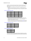
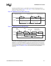
• Data: data is transferred serially between the controller and the card in 8-bit blocks at rates up
to 20 Mbps. The format for the data token depends on the card’s mode. Table 15-2 shows the
data token format for MMC mode and Table 15-3 shows the data token format for SPI mode.
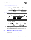
In MMC mode, all operations contain command tokens and most commands have an associated
response token. Read and write commands also have a data token. Command and response tokens
are sent and received on the bidirectional MMCMD signal and data tokens are sent and received on
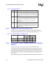
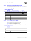
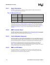
Table 15-1. Command Token Format
Bit Position Width (bits) Value Description
47 1 0 start bit
46 1 1 transmission bit
[45:40] 6 x command index
[39:8] 32 x argument
[7:1] 7 x CRC7
0 1 1 end bit
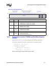
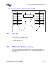
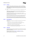
Table 15-2. MMC Data Token Format
Stream Data Block Data Description
1 0 start bit
x x data
no CRC x CRC7
1 1 end bit
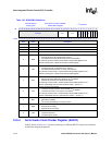
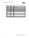
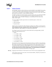
Table 15-3. SPI Data Token Format
Value Description
11111110 start byte
x data
xCRC16