


4-32 Intel® PXA255 Processor Developer’s Manual
System Integration Unit
4.3.3 Trim Procedure
The HZ clock driving the RTC is generated by dividing the output of the oscillator multiplexor. The
inherent inaccuracies of crystals, aggravated by varying capacitance of the board connections, as
well as other variables, may cause the time base to be somewhat inaccurate. This requires a slight
adjustment in the desired clock period. The processor, through the RTTR, lets you adjust (or trim)
the HZ time base to an error of less than 1ppm. Such that if the HZ clock is set to be 1 Hz, there
would be an error of less than 5 seconds per month.
The RTTR is reset to its default value of 0x0000_7FFF each time the nRESET signal is asserted.
This yields approximately a 1 Hz clock.
When the clock divisor count (RTTR[15:0]) is set to 0x0, the HZ clock feeding the RTC maintains
a high level signal - essentially disabling the RTC. For all non-zero values programmed into the
clock divisor count, the HZ clock frequency will be the 32 kHz clock source divided by the clock
divisor count plus 1.
4.3.3.1 Oscillator Frequency Calibration
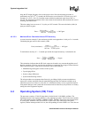
To determine the value programmed into the RTTR, you must first measure the output frequency at
the oscillator multiplexor (approximately 32 kHz) using an accurate time base, such as a frequency
counter. This clock is externally visible by selecting the alternate function for GPIO[12] or
GPIO[72]. To gain access to the clock, program this pin as an output and then switch to the
alternate function. Refer to Section 4.1, for details on how to make the clock externally visible. To
trim the clock, divide the output of the oscillator by an integer value and fractional adjust it by
periodically deleting clocks from the stream driving this integer divider.
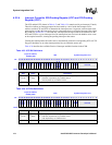
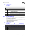
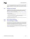
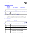
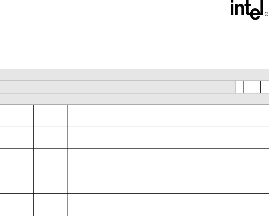
Table 4-40. RTSR Bit Definitions
Physical Address
0x4090_0008
RTSR System Integration Unit
Bit
31 30 29 28 27 26 25 24 23 22 21 20 19 18 17 16 15 14 13 12 11 10 9 8 7 6 5 4 3 2 1 0
reserved
HZE
ALE
HZ
AL
Reset ? ? ? ? ? ? ? ? ? ? ? ? / ? ? ? ? ? ? ? ? ? ? ? ? ? ? ? 0 0 0 0
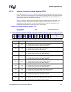
Bits Name Description
<31:4> — reserved
<3> HZE
HZ interrupt enable.
0 – The HZ interrupt is not enabled.
1 – The HZ interrupt is enabled.
<2> ALE
RTC alarm interrupt enable.
0 – The RTC alarm interrupt is not enabled.
1 – The RTC alarm interrupt is enabled.
<1> HZ
HZ rising-edge detected.
0 – No rising edge has been detected.
1 – A rising edge has been detected and HZE bit is set.
<0> AL
RTC alarm detected.
0 – No RTC alarm has been detected.
1 – An RTC alarm has been detected (RTNR matches RCAR).and ALE bit is set