


2-14 Intel® PXA255 Processor Developer’s Manual
System Architecture
MMCCLK/
GP[6]
ICOCZ
MMC clock. (output) Clock signal for the MMC
Controller.
Pulled High -
Note[1]
Note [3]
MMCCS0/
GP[8]
ICOCZ
MMC chip select 0. (output) Chip select 0 for the MMC
Controller.
Pulled High -
Note[1]
Note [3]
MMCCS1/
GP[9]
ICOCZ
MMC chip select 1. (output) Chip select 1 for the MMC
Controller.
Pulled High -
Note[1]
Note [3]
SSP Pins
SSPSCLK/
GPIO[23]
ICOCZ Synchronous Serial Port Clock. (output)
Pulled High -
Note[1]
Note [3]
SSPSFRM/
GPIO[24]
ICOCZ Synchronous Serial Port Frame. (output)
Pulled High -
Note[1]
Note [3]
SSPTXD/
GPIO[25]
ICOCZ Synchronous Serial Port Transmit. (output)
Pulled High -
Note[1]
Note [3]
SSPRXD/
GPIO[26]
ICOCZ Synchronous Serial Port Receive. (input)
Pulled High -
Note[1]
Note [3]
SSPEXTCLK/
GPIO[27]
ICOCZ Synchronous Serial Port External Clock. (input)
Pulled High -
Note[1]
Note [3]
Network SSP pins
NSSPSCLK/
GPIO[81]
ICOCZ Network Synchronous Serial Port Clock.
Pulled High
Note [1]
Note [3]
NSSPSFRM/
GPIO[82]
ICOCZ Network Synchronous Serial Port Frame Signal.
Pulled High
Note [1]
Note [3]
NSSPTXD/
GPIO[83]
ICOCZ Network Synchronous Serial Port Transmit.
Pulled High
Note [1]
Note [3]
NSSPRXD/
GPIO[84]
ICOCZ Network Synchronous Serial Port Receive.
Pulled High
Note [1]
Note [3]
USB Client Pins
USB P IAOAZ USB Client Positive. (bidirectional) Hi-Z Hi-Z
USB N IAOAZ USB Client Negative pin. (bidirectional) Hi-Z Hi-Z
AC97 Controller and I
2
S Controller Pins
BITCLK/
GPIO[28]
ICOCZ
AC97 Audio Port bit clock. (input) AC97 clock is
generated by Codec 0 and fed into the PXA255
processor and Codec 1.
AC97 Audio Port bit clock. (output) AC97 clock is
generated by the PXA255 processor.
I
2
S bit clock. (input) I2S clock is generated externally
and fed into PXA255 processor.
I
2
S bit clock. (output) I
2
S clock is generated by the
PXA255 processor.
Pulled High -
Note[1]
Note [3]
SDATA_IN0/
GPIO[29]
ICOCZ
AC97 Audio Port data in. (input) Input line for Codec 0.
I
2
S data in. (input) Input line for the I
2
S Controller.
Pulled High -
Note[1]
Note [3]
SDATA_IN1/
GPIO[32]
ICOCZ
AC97 Audio Port data in. (input) Input line for Codec 1.
I
2
S system clock. (output) System clock from I
2
S
Controller.
Pulled High -
Note[1]
Note [3]
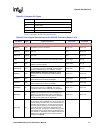
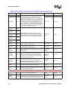
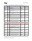
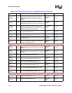
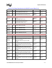
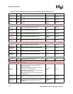
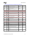
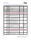
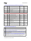
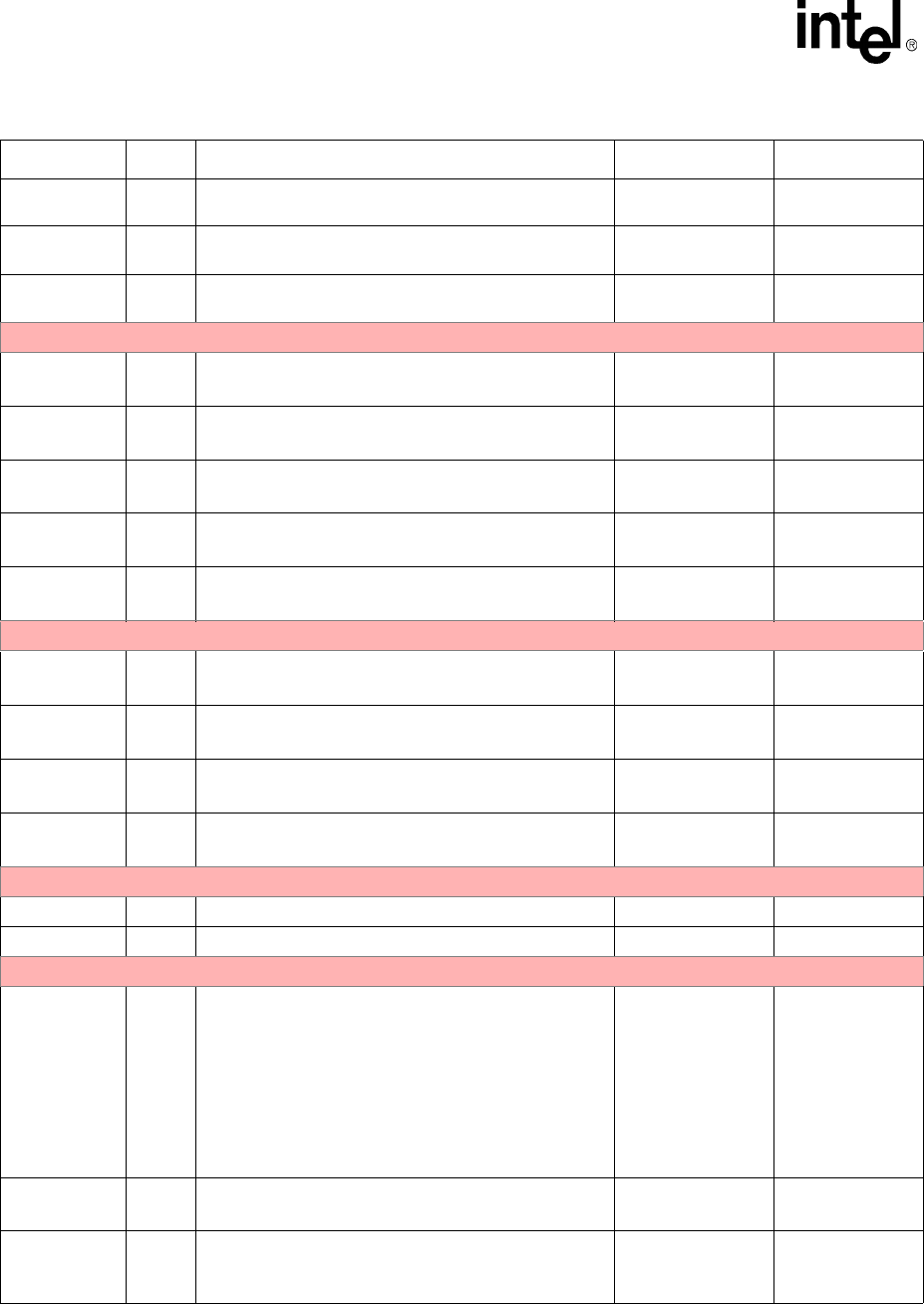
Table 2-6. Pin & Signal Descriptions for the PXA255 Processor (Sheet 6 of 9)
Pin Name Type Signal Descriptions Reset State Sleep State