


Intel® PXA255 Processor Developer’s Manual 14-13
Inter-Integrated-Circuit Sound (I2S) Controller
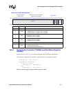
The reset value, 0x0000001A, defaults to a sampling frequency of 22.05 kHz.
Note: Setting this register to values other than those shown in Section 14.2 is not allowed and will cause
unpredictable activity.
This is a read/write register. Ignore reads from reserved bits. Write zeros to reserved bits.
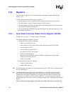
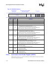
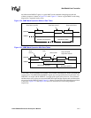
14.6.5 Serial Audio Interrupt Clear Register (SAICR)
SAICR, shown in Table 14-9, is the Interrupt Control Register. This is only an addressable location
and no data is actually stored. These addressable locations are used only for clearing status register
(SASR0) bits. Each bit position corresponds to an interrupt source bit position in the Status
register.
This is a write-only register. Write zeros to reserved bits.
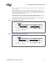
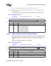
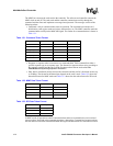
Table 14-8. SADIV Bit Definitions
Physical Address
0x4040_0060
Serial Audio Clock Divider Register I
2
S Controller
Bit
31 30 29 28 27 26 25 24 23 22 21 20 19 18 17 16 15 14 13 12 11 10 9 8 7 6 5 4 3 2 1 0
reserved SADIV
Reset
0 0 0 0 0 0 0 0 0 0 0 0 0 0 0 0 0 0 0 0 0 0 0 0 0 0 0 1 1 0 1 0
Bits Name Description
31:7 — reserved
6:0 SADIV
Audio clock divider. Valid SADIV(6:0) are:
000 1100 – BITCLK of 3.072MHz
000 1101 – BITCLK of 2.836 MHz
001 1010 – BITCLK of 1.418MHz
010 0100 – BITCLK of 1.024MHz
011 0100 – BITCLK of 708.92 KHz
100 1000 – BITCLK of 512.00 KHz
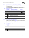
Table 14-9. SAICR Bit Definitions
Physical Address
0x4040_0018
Serial Audio Interrupt Clear Register I
2
S Controller
Bit
31 30 29 28 27 26 25 24 23 22 21 20 19 18 17 16 15 14 13 12 11 10 9 8 7 6 5 4 3 2 1 0
reserved
ROR
TUR
reserved
Reset
r r r r r r r r r r r r r r r r r r r r r r r r r r r r r r r r
Bits Name Description
31:7 — reserved
6 ROR Clear Receive FIFO overrun Interrupt and ROR status bit in SASR0.
5 TUR Clear Transmit FIFO under-run Interrupt and TUR status bit in SASR0.
4:0 — reserved