


7-36 Intel® PXA255 Processor Developer’s Manual
LCD Controller
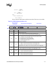
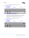
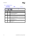
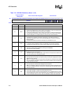
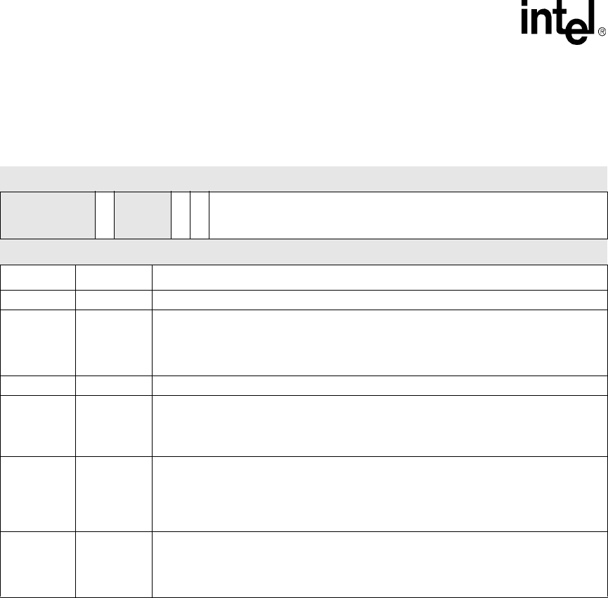
Table 7-10. LDCMDx Bit Definitions
Physical Address
channel 0: 0x4400_020C
channel 1: 0x4400_021C
LDCMD0
LDCMD1
LCD Controller
Bit
31 30 29 28 27 26 25 24 23 22 21 20 19 18 17 16 15 14 13 12 11 10 9 8 7 6 5 4 3 2 1 0
reserved
PAL
reserved
SOFINT
EOFINT
LEN
Reset
X X X X X 0 X X X 0 0 0 0 0 0 0 0 0 0 0 0 0 0 0 0 0 0 0 0 0 0 0
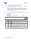
Bits Name Description
31:27 — reserved
26 PAL
Load Palette:
0 = DMA in progress is not the palette buffer.
1 = DMA in progress is the palette buffer.
PAL must not be set in LDCMD1.
25:23 — reserved
22 SOFINT
Start of Frame Interrupt:
0 = Do not set the SOF interrupt bit in the LCD status register when starting a new frame.
1 = Set the start of frame (SOF) interrupt bit in the LCD status register when starting a new
frame (after loading the frame descriptor).
21 EOFINT
End of Frame Interrupt:
0 = Do not set the EOF interrupt bit in the LCD status register when finished fetching the
last word of this frame.
1 = Set the end of frame (EOF) interrupt bit in the LCD status register when finished
fetching the last word of this frame.
20:0 LEN
Length of transfer in bytes:
The two lowest bits [1:0] are part of the length calculation but must always be zero for
proper memory alignment.
LEN = 0 is illegal.