


Intel® PXA255 Processor Developer’s Manual 7-37
LCD Controller
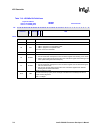
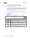
7.6.6 LCD DMA Frame Branch Registers (FBRx)
FBRx, one for each DMA channel, shown in Table 7-11, contain the addresses, aligned on a 4-byte
boundary, of the descriptors to branch to.
When BRA is set, the Frame Descriptor Address Register is ignored. The next descriptor is fetched
from the address in FBRx[31:4], regardless of whether frame data or palette RAM data is being
processed. Setting BINT to one forces the DMAC to set the Branch Status interrupt bit (BS) in the
LCD Controller Status Register after fetching the branched-to descriptor. BRA is automatically
cleared by hardware when the branch is taken.
Note: In dual-panel mode, both FBR0 and FBR1 must be written in order to branch properly.
These are read/write registers. Ignore reads from reserved bits. Write zeros to reserved bits.
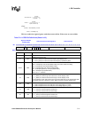
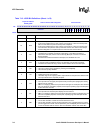
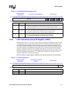
Table 7-11. FBRx Bit Definitions
Physical Address
channel 0: 0x4400_0020
channel 1: 0x4400_0024
LCD DMA Frame Branch Registers LCD Controller
Bit
31 30 29 28 27 26 25 24 23 22 21 20 19 18 17 16 15 14 13 12 11 10 9 8 7 6 5 4 3 2 1 0
Frame Branch Address
reserved
BINT
BRA
Reset 0 0 0 0 0 0 0 0 0 0 0 0 0 0 0 0 0 0 0 0 0 0 0 0 0 0 0 0 X X 0 0
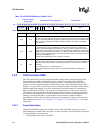
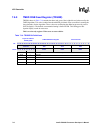
Bits Name Description
31:4
Frame
Branch
Address
Frame Branch Address:
Address of the descriptor for the branched-to frame.
3:2 — reserved
1BINT
Branch Interrupt:
0 = Do not set the BS interrupt bit in register LCSR after the branched-to descriptor is
loaded.
1 = Set the BS interrupt bit in register LCSR after the branched-to descriptor is loaded.
0BRA
Branch:
0 = Do not branch after finishing the current frame.
1 = Branch after finishing the current frame. The next descriptor will be fetched from the
Frame Branch Address. BRA is automatically cleared after loading the new descriptor.