


Intel® PXA255 Processor Developer’s Manual 16-11
Network SSP Serial Port
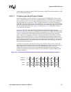
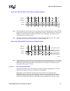
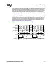
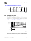
clocks programmed in the field SSPSP[SFRMP]. The SSPSFRM remains asserted for the number
of half-clocks programmed within SSPSP[SFRMWDTH]. Four to 32-bits can be transferred per
frame. Once the LSB transfers, the SSPSCLK continues toggling based on the dummy stop field
(SSPSP[DMYSTOP]). SSPTXD either retains the last value transmitted or is forced to zero,
depending on the value programmed within the end of transfer data state field (SSPSP[ETDS]),
when the controller goes into idle mode, unless the SSP is disabled or reset (which forces SSPTXD
low). Refer to Table 16-2 for more information.
With the assertion of SSPSFRM, receive data is simultaneously driven from the peripheral on
SSPRXD, MSB first. Data transitions on SSPSCLK based on the serial clock mode selected and
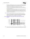
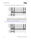
are sampled by the controller on the opposite edge. When the SSP is a master to the frame sync
(SSPSFRM) and a slave to the clock (SSPSCLK), at least three extra clocks are needed at the
beginning and end of each block of transfers to synchronize internal control signals (a block of
transfers is a group of back-to-back continuous transfers).
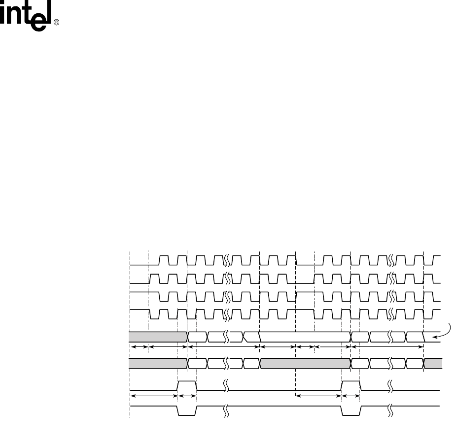
Figure 16-9. Programmable Serial Protocol (multiple transfers)
A9523-02
SSPSCLK
(when SCMODE = 0)
SSPSCLK
(when SCMODE = 1)
SSPSCLK
(when SCMODE = 2)
SSPSCLK
(when SCMODE = 3)
SSPSFRM
(when SFRMP = 1)
SSPSFRM
(when SFRMP = 0)
SSPTXD
SSPRXD
MSBUndefined
T1 T2 T3 T3
MSB LSB
End of
Transfer
Data State
LSB
End of Transfer
Data State
MSB MSB LSBLSB
T1 T2
T6T5 T5 T6
T4
Undefined Undefined
Un-
defined