


Intel® PXA255 Processor Developer’s Manual 3-3
Clocks and Power Manager
The clocks manager also contains clock gating for power reduction.
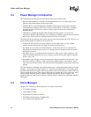
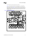
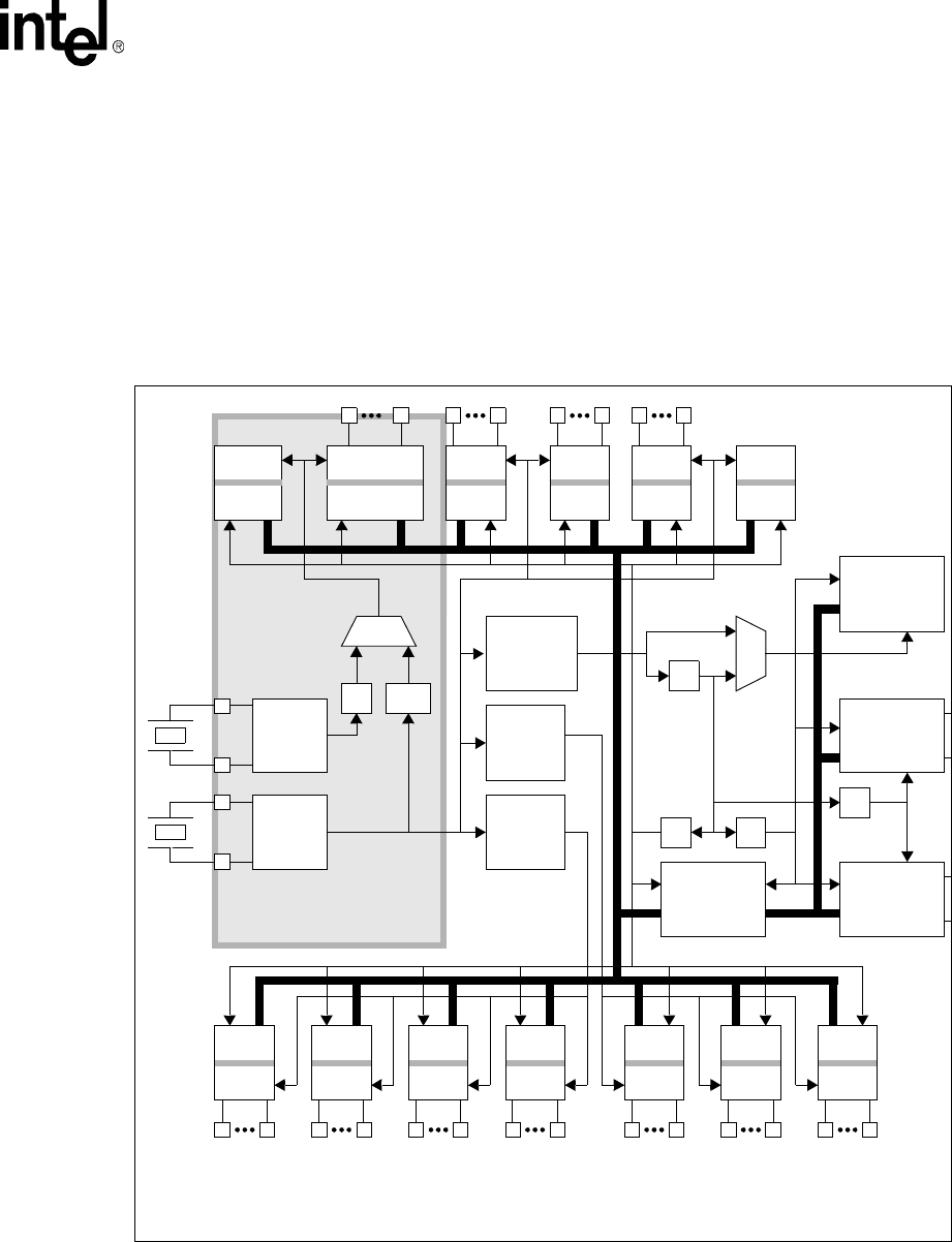
Figure 3-1 shows a functional representation of the clocking network. “L” is in the core PLL.
The PXbus is the internal bus between the Core, the DMA/Bridge, the LCD Controller, and the
Memory Controller as shown in Figure 3-1. This bus is clocked at 1/2 the run mode frequency. For
optimal performance, the PXbus should be clocked as fast as possible. For example, if a target core
frequency of 200 MHz is desired use 200 MHz run mode instead of 200 MHz turbo mode with run
at 100 MHz. Increasing the PXbus frequency may help reduce the latency involved in accessing
non-cacheable memory.
Figure 3-1. Clocks Manager Block Diagram
/N
/M
/4
DMA
/
Bridge
/1 /112
UARTs
14.746
AC97
12.288
I2S
5.672
PWM
3.6864
SSP
3.6864
GPIO
3.6864
OST
3.6864
PWR_MGR
32.768 k
32.768
kHz
OSC
3.6864
MHz
OSC
100-400
MHz
PLL*
95.846
MHz
PLL
147.46
MHz
PLL
CORE
CPU
Controller
MEM
Controller
LCD
/2
MMC
19.169
I2C
31.949
FICP
47.923
USB
47.923
RTC
32.768 k
RETAINS POWER IN SLEEP
PXbus