


Intel® PXA255 Processor Developer’s Manual 14-7
Inter-Integrated-Circuit Sound (I2S) Controller
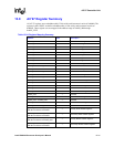
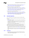
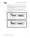
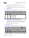
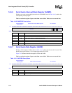
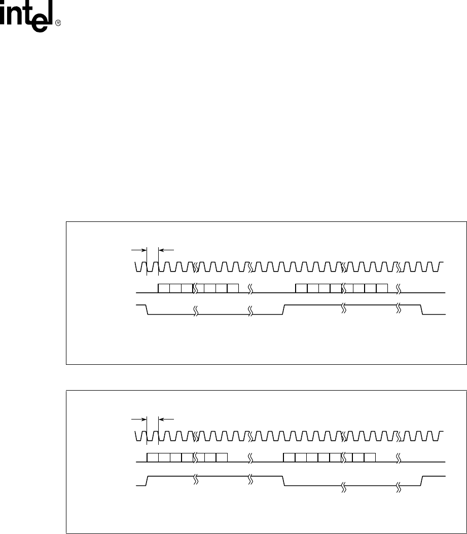
Figure 14-1 and Figure 14-2 provide timing diagrams that show formats for I
2
S and MSB-justified
modes of operations.
Data is transmitted and received in frames of 64 BITCLK cycles. Each frame consists of a Left
sample and a Right sample. Each frame holds 16-bits of valid sample data (shown in the figures)
and 16-bits of padded zeros (not shown in the figures). The transmit and receive FIFOs only hold
valid sample data (not padded zero data).
In the Normal I
2
S mode, the SYNC is low for the Left sample and high for the Right sample. Also,
the MSB of each data sample lags behind the SYNC edges by one BITCLK cycle.
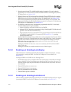
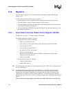
In the MSB-Justified mode, the SYNC is high for the Left sample and low for the Right sample.
Also, the MSB of each data sample is aligned with the SYNC edges.
Figure 14-1. I
2
S Data Formats (16 bits)
Figure 14-2. MSB-Justified Data Formats (16 bits
A8842-01
SYNC
BITCLK
Note: Timing for SData_In is identical to SData_Out.
SData_Out
cycle0
Left Right
012
15 14 13 3 2 1 0
15 14 13 12 3 2 1 0
3 13 141516 293031 323334 35 45464748 6263 0
A8843-01
SYNC
BITCLK
Note: Timing for SData_In is identical to SData_Out.
SData_Out
cycle0
Left Right
012
15 14 13 3 2 1 0
15 14 13 12 3 2 1 0
3 13 141516 293031 323334 35 45464748 6263 0