


Intel® PXA255 Processor Developer’s Manual 9-27
I
2
C Bus Interface Unit
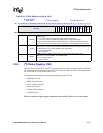
9.9.5 I
2
C Slave Address Register (ISAR)
The ISAR, shown in Table 9-12, defines the I
2
C unit’s 7-bit slave address. In slave-receive mode,
the processor responds when the 7-bit address matches the value in this register. The processor
writes this register before it enables I
2
C operations. The ISAR is fully programmable (no address is
assigned to the I
2
C unit) so it can be set to a value other than those of hard-wired I
2
C slave
peripherals in the system. If the processor is reset, the ISAR is not affected. The ISAR register
default value is 0000000
2
.
This is a read/write register. Ignore reads from reserved bits. Write zeros to reserved bits.
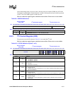
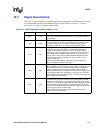
1 ACKNAK
ACK/NAK Status:
0 = I
2
C unit received or sent an ACK on the bus.
1 = I
2
C unit received or sent a NAK.
Used in slave-transmit mode to determine when the transferred byte is the last one.
Updated after each byte and ACK/NAK information is received.
0RWM
Read/Write Mode:
0 = I
2
C unit is in master-transmit or slave-receive mode.
1 = I
2
C unit is in master-receive or slave-transmit mode.
R/nW bit of the slave address. Automatically cleared by hardware after a stop state.
Table 9-11. ISR Bit Definitions (Sheet 2 of 2)
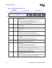
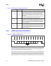
Physical Address
4030_1698
I
2
C Status Register I
2
C Bus Interface Unit
Bit
31 30 29 28 27 26 25 24 23 22 21 20 19 18 17 16 15 14 13 12 11 10 9 8 7 6 5 4 3 2 1 0
reserved
BED
SAD
GCAD
IRF
ITE
ALD
SSD
IBB
UB
ACKNAK
RWM
Reset 0 0 0 0 0 0 0 0 0 0 0 0 0 0 0 0 0 0 0 0 0 0 0 0 0 0 0 0 0 0 0 0
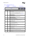
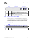
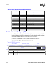
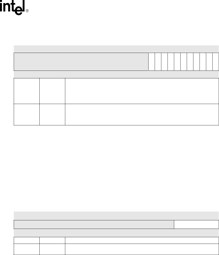
Table 9-12. ISAR Bit Definitions
Physical Address
4030_16A0
I
2
C Slave Address Register I
2
C Bus Interface Unit
Bit
31 30 29 28 27 26 25 24 23 22 21 20 19 18 17 16 15 14 13 12 11 10 9 8 7 6 5 4 3 2 1 0
reserved ISA
Reset
0 0 0 0 0 0 0 0 0 0 0 0 0 0 0 0 0 0 0 0 0 0 0 0 0 0 0 0 0 0 0 0
31:7 — reserved
6:0 ISA
I
2
C Slave Address: 7-bit address that the I
2
C unit responds to when in slave-receive
mode.