Intel® PXA255 Processor Developer’s Manual 16-9
Network SSP Serial Port
SSPRXD is undefined before the MSB and after the LSB is transmitted. For minimum power
consumption, this pin must not float.
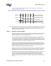
Note: When configured as either master or slave (to clock or frame) the SSP continues to drive SSPTXD
with the last bit of data sent (the LSB). If SSCR0[SSE] is cleared, SSPTXD goes low. The state of
SSPRXD is undefined before the MSB and after the LSB is transmitted. For minimum power
consumption, this pin must not float.
16.4.3.3 Microwire* Protocol Details
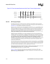
The Microwire* protocol is similar to SPI, except transmission is half-duplex instead of full-duplex
and it uses master-slave message passing. While in the idle state or when the SSP is disabled,
SSPSCLK and SSPTXD are low and SSPSFRM is high.
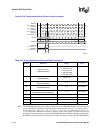
Each serial transmission begins with SSPSFRM asserting low, followed by an eight or 16-bit
command word sent from the controller to the peripheral on SSPTXD. The command word data
size is selected by the Microwire* transmit data size bit (SSCR1[MWDS]). SSPRXD is controlled
by the peripheral and remains in a high-impedance state. SSPSCLK asserts high midway into the
command’s most significant bit and continues toggling at the bit rate.
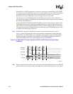
One bit-period after the last command bit, the peripheral returns the serial-data requested most
significant bit first on SSPRXD. Data transitions on the falling edge of SSPSCLK and is sampled
on the rising edge. The last falling edge of SSPSCLK coincides with the end of the last data bit on
SSPRXD and SSPSCLK remains low after that (if it is the only word or the last word of the
transfer). SSPSFRM de-asserts high one-half clock period later.
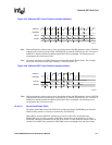
The start and end of a series of back-to-back transfers are like those of a single transfer; however,
SSPSFRM remains asserted (low) throughout the transfer. The end of a data word on SSPRXD is
followed immediately by the start of the next command byte on SSPTXD with no dead time.
When using the Microwire* protocol, the SSP can function only as a master (frame and clock are
outputs). Therefore, both SSCR1[SCLKDIR] and SSCR0[SFRMDIR] must both be cleared.
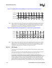
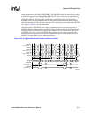
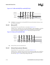
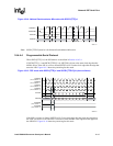
Figure 16-7 shows the National Semiconductor Microwire* frame protocol with eight-bit
command words when back-to-back frames are transmitted. Figure 16-8 shows the National
Semiconductor Microwire* frame protocol with eight-bit command words for a single transmitted
frame.
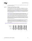
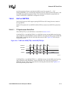
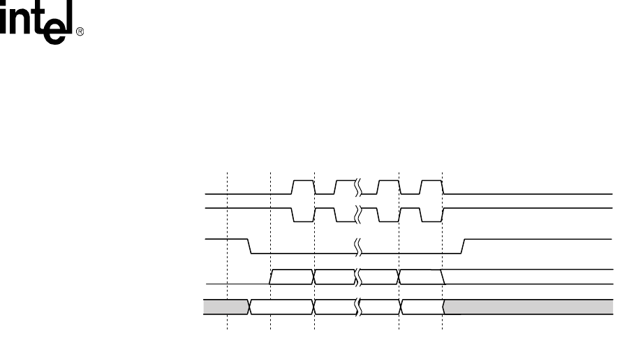
Figure 16-6. Motorola SPI* Frame Protocols for SPO and SPH Programming (single transfers)
A9520-02
SSPRXD
SSPSFRM
SSPSCLK
SPO=0
SSPSCLK
SPO=1
SSPTXD
MSB 4 to 32 Bits LSB
Bit[N] Bit[N-1] Bit[1] Bit[0]
Bit[N] Bit[N-1] Bit[1] Bit[0]
Undefined Undefined
End of Transfer Data State


