


5-22 Intel® PXA255 Processor Developer’s Manual
DMA Controller
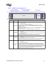
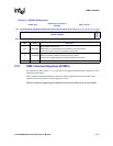
5.3.6 DMA Target Address Registers (DTADRx)
To software, DTADRx (Table 5-11) is read only in the Descriptor Fetch Mode and is read/write in
the No-Descriptor Fetch Mode.
These registers contain the target address for the current descriptor in a channel. The target address
is the address of an internal peripheral or a memory location. On power up, the bits in this register
are undefined. If the target address is the address of a companion chip or external peripheral, the
target address must be aligned to an 8-byte boundary. This allows bits [2:0] of the address to be
reserved. If the target address is the address for an internal peripheral, the address must be 32-bit
aligned so that bits [1:0] are reserved. DTADRx must not contain the address of any other internal
DMA, LCD, or MEMC register.
The DTADRx must not contain a flash address because writes to flash from the DMAC are not
supported.
This is a read/write register. Ignore reads from reserved bits. Write zeros to reserved bits.
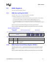
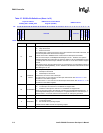
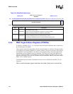
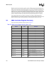
Table 5-10. DSADRx Bit Definitions
0x4000_02x4
DMA Source Addr Register
(DSADRx)
DMA Controller
Bit
31 30 29 28 27 26 25 24 23 22 21 20 19 18 17 16 15 14 13 12 11 10 9 8 7 6 5 4 3 2 1 0
SOURCE ADDRESS
reserved
Reset Uninitialized
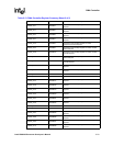
Bits Name Description
31:3 SRCADDR
Source Address (read / write).
Address of the internal peripheral or address of a memory location.
Address of a memory location for companion -chip transfer
2 SRCADDR
Source Address Bit 2
Reserved if DSADR.SrcAddr is an external memory location
Not reserved if DSADR.SrcAddr is an internal peripheral (read / write).
1:0 — reserved