


Intel® PXA255 Processor Developer’s Manual 17-13
Hardware UART
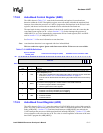
17.5.5 Interrupt Identification Register (IIR)
The UART prioritizes interrupts in four levels (see Table 17-7) and records them in the IIR. The
IIR stores information that indicates that a prioritized interrupt is pending and identifies the source
of the interrupt. The Interrupt Identification Register (IIR) bit definitions are shown in Table 17-8.
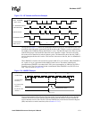
If additional data is received before a receiver time out interrupt is serviced, the interrupt is
deasserted.
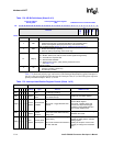
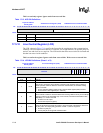
Read IIR to determine the type and source of UART interrupts. To be 16550 compatible, the lower
4 bits of the IIR are priority encoded, shown in Table 17-9. If two or more interrupts represented by
these bits occur, only the interrupt with the highest priority is displayed. The autobaud lock
interrupt is not priority encoded. It asserts/deasserts independently of the lower 4 bits.
IIR[nIP] indicates the existence of an interrupt in the lower four bits of the IIR. A low signal on this
bit indicates an encoded interrupt is pending. If this bit is high, no encoded interrupt is pending,
regardless of the state of the other 3 bits. nIP has no effect or association with IIR[ABL], which
asserts/deasserts independently of nIP.
This is a read-only register. Ignore reads from reserved bits.
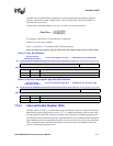
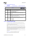
Table 17-7. Interrupt Conditions
Priority Level Interrupt origin
1 (highest) Receiver line status – One or more error bits were set.
2
Received data is available. In FIFO mode, trigger threshold was reached. In non-FIFO mode,
RBR has data.
2
Receiver timeout occurred. Occurs only in FIFO mode, when data is in the receive FIFO but no
data has been sent for a set time period.
3
Transmitter requests data. In FIFO mode, the transmit FIFO is at least half empty. In non-FIFO
mode, the THR has been transmitted.
4 (lowest) Modem status – One or more modem input signal has changed state.
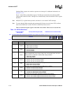
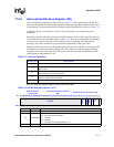
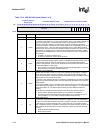
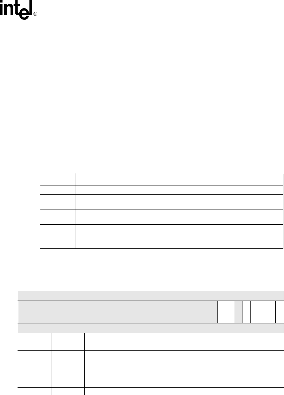
Table 17-8. IIR Bit Definitions (Sheet 1 of 2)
Physical Address
0x4160_0008
Interrupt Identification Register
(IIR)
PXA255 Processor Hardware UART
Bit
31 30 29 28 27 26 25 24 23 22 21 20 19 18 17 16 15 14 13 12 11 10 9 8 7 6 5 4 3 2 1 0
reserved
FIFOES
reserved
ABL
TOD
IID
nIP
Reset ? ? ? ? ? ? ? ? ? ? ? ? ? ? ? ? ? ? ? ? ? ? ? ? 0 0 ? 0 0 0 0 1
Bits Name Description
31:8 — reserved
7:6 FIFOES[1:0]
FIFO MODE ENABLE STATUS:
00 – Non-FIFO mode is selected
01 – reserved
10 – reserved
11 – FIFO mode is selected (TRFIFOE = 1)
5 — reserved