


Intel® PXA255 Processor Developer’s Manual 4-23
System Integration Unit
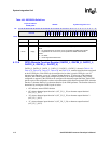
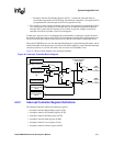
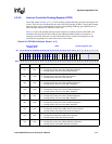
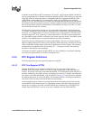
4.2.2.3 Interrupt Controller Control Register (ICCR)
The ICCR, shown in Table 4-32, contains a single control bit, Disable Idle Mask (DIM). In normal
Idle mode any enabled interrupt can bring the processor out of Idle mode regardless of the value in
ICMR. If this bit is set, then the interrupts that can bring the processor out of Idle mode are defined
by the ICMR.
Note: This register is cleared during all resets.
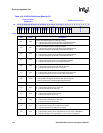
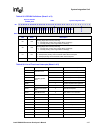
Table 4-36 describes the available first-level interrupts and their location in the ICPR.
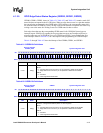
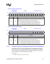
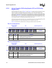
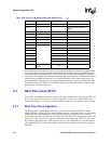
Table 4-31. ICLR Bit Definitions
Physical Address
0x40D0_0008
ICLR System Integration Unit
Bit
31 30 29 28 27 26 25 24 23 22 21 20 19 18 17 16 15 14 13 12 11 10 9 8 7 6 5 4 3 2 1 0
IL31
IL30
IL29
IL28
IL27
IL26
IL25
IL24
IL23
IL22
IL21
IL20
IL19
IL18
IL17
reserved
reserved
IL14
IL13
IL12
IL11
IL10
IL9
IL8
reserved
Reset
0 0 0 0 0 0 0 0 0 0 0 0 0 0 0 0 0 0 0 0 0 0 0 0 ? ? ? ? ? ? ? ?
Bits Name Description
<31:8> IL[x]
Interrupt Level ‘x’ (where n = 8 through 14 and 17 through 31).
0 – Interrupt routed to IRQ interrupt input.
1 – Interrupt routed to FIQ interrupt input.
<7:0> — reserved
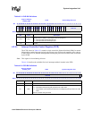
Table 4-32. ICCR Bit Definitions
Physical Address
0x40D0_0014
ICCR System Integration Unit
Bit
31 30 29 28 27 26 25 24 23 22 21 20 19 18 17 16 15 14 13 12 11 10 9 8 7 6 5 4 3 2 1 0
reserved
DIM
Reset ? ? ? ? ? ? ? ? ? ? ? ? ? ? ? ? ? ? ? ? ? ? ? ? ? ? ? ? ? ? ? 0
Bits Name Description
<31:1> — reserved
<0> DIM
Disable Idle mask.
0 – All enabled interrupts bring
the processor out of idle mode.
1 – Only enabled and unmasked (as defined in the ICMR) bring
the processor out of idle
mode.
This bit is cleared during all resets.